How to Use Arduino Nano: Examples, Pinouts, and Specs
Introduction
The Arduino Nano is a compact and versatile microcontroller board based on the ATmega328P microcontroller. It is a breadboard-friendly board that retains the functionalities of the larger Arduino boards but in a smaller form factor. The Nano is particularly popular in prototyping, educational contexts, and embedded system development due to its ease of use and extensive support community. Common applications include DIY electronics projects, robotics, sensor interfacing, and interactive artworks.
Explore Projects Built with Arduino Nano


Explore Projects Built with Arduino Nano
Technical Specifications
Key Technical Details
- Microcontroller: ATmega328P
- Operating Voltage: 5V
- Input Voltage (recommended): 7-12V
- Input Voltage (limits): 6-20V
- Digital I/O Pins: 14 (of which 6 provide PWM output)
- Analog Input Pins: 8
- DC Current per I/O Pin: 40 mA
- DC Current for 3.3V Pin: 50 mA
- Flash Memory: 32 KB (ATmega328P) of which 2 KB used by bootloader
- SRAM: 2 KB (ATmega328P)
- EEPROM: 1 KB (ATmega328P)
- Clock Speed: 16 MHz
- LED_BUILTIN: Pin 13
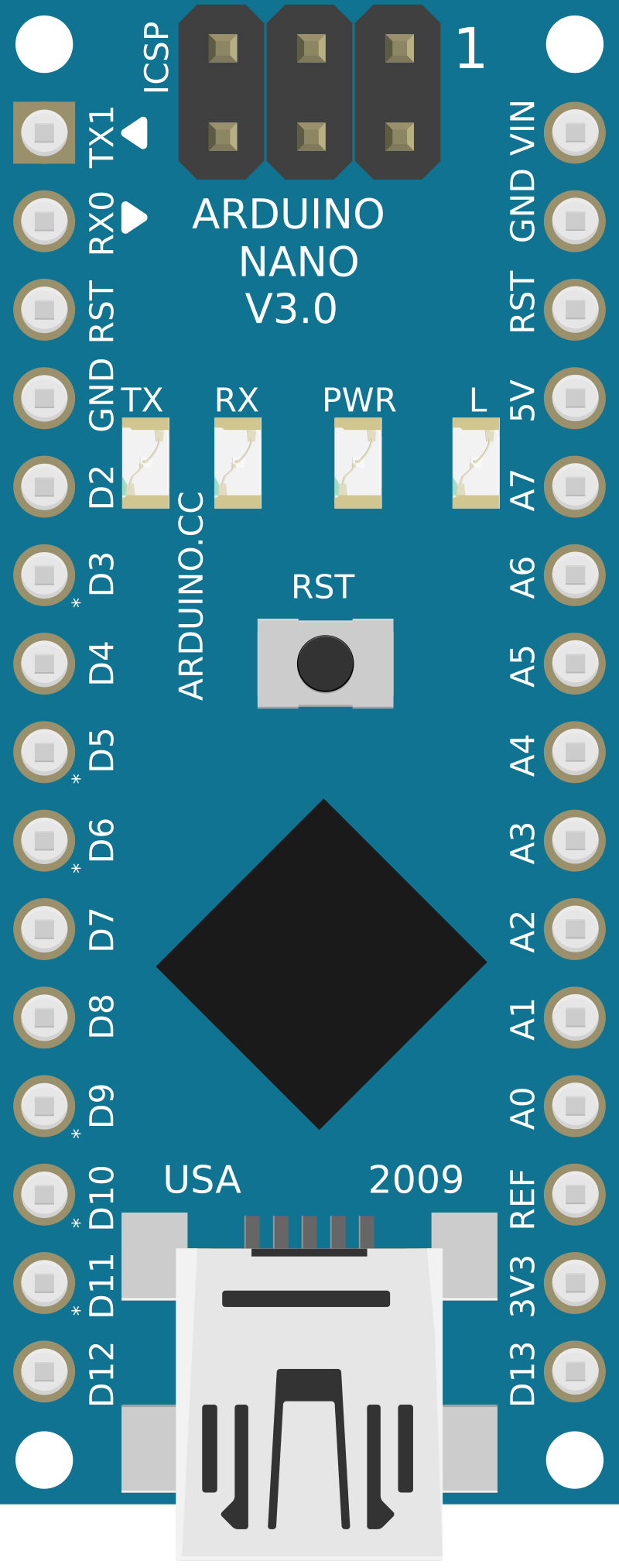
Pin Configuration and Descriptions
| Pin Number | Function | Description |
|---|---|---|
| 1 | RESET | Used to reset the microcontroller |
| 2-3 | D0/D1 (RX/TX) | Serial communication pins |
| 4-9 | D2-D7 | Digital I/O pins |
| 10-13 | D8-D11 (PWM) | Digital I/O with PWM capability |
| 14-15 | D12-D13 | Digital I/O pins (D13 is also connected to LED) |
| 16-23 | A0-A7 | Analog input pins or digital I/O |
| 24 | AREF | Analog reference voltage for the ADC |
| 25 | 3V3 | 3.3V output (derived from the FTDI chip) |
| 26 | D13 (LED) | Built-in LED connected to digital pin 13 |
| 27-30 | GND | Ground pins |
| 31-32 | 5V | 5V power supply from the USB or VIN pin |
| 33 | RST | Reset pin, can be used to reset the microcontroller |
| 34 | VIN | Input voltage to the Arduino board |
Usage Instructions
How to Use the Arduino Nano in a Circuit
Powering the Board:
- You can power the Arduino Nano by connecting the USB cable from your computer to the Nano's mini-USB port.
- Alternatively, you can supply voltage through the VIN pin (7-12V recommended).
Connecting to a Breadboard:
- Insert the Arduino Nano into a breadboard to easily connect other components to the board's pins.
Programming the Board:
- Connect the Nano to your computer using a mini-USB cable.
- Select "Arduino Nano" from the Tools > Board menu in the Arduino IDE.
- Choose the correct serial port from Tools > Port.
- Write or open your sketch and click the "Upload" button to program the Nano.
Using Digital I/O:
- Configure pins as INPUT or OUTPUT using
pinMode(pin, mode);. - Read digital inputs using
digitalRead(pin);. - Set digital outputs using
digitalWrite(pin, value);.
- Configure pins as INPUT or OUTPUT using
Using Analog Inputs:
- Read analog inputs using
analogRead(pin);. - The default reference voltage is 5V, but it can be changed with
analogReference().
- Read analog inputs using
Using PWM Outputs:
- Use
analogWrite(pin, value);to output PWM signals on pins 3, 5, 6, 9, 10, and 11.
- Use
Important Considerations and Best Practices
- Do not exceed the voltage limits on the VIN pin as it can damage the board.
- Ensure that the total current drawn from the I/O pins does not exceed the specified limits.
- Use external power supplies when connecting components that require more current than the Nano can provide.
- Always disconnect the board from power sources before making or altering connections.
Example Code for Blinking an LED
// The setup function runs once when you press reset or power the board
void setup() {
  // initialize digital pin LED_BUILTIN as an output.
  pinMode(LED_BUILTIN, OUTPUT);
}

// The loop function runs over and over again forever
void loop() {
  digitalWrite(LED_BUILTIN, HIGH);   // turn the LED on (HIGH is the voltage level)
  delay(1000);                       // wait for a second
  digitalWrite(LED_BUILTIN, LOW);    // turn the LED off by making the voltage LOW
  delay(1000);                       // wait for a second
}
Troubleshooting and FAQs
Common Issues
Nano not recognized by computer:
- Check the USB cable and connections.
- Ensure the correct drivers are installed.
- Try a different USB port or computer.
Sketch not uploading:
- Verify that the correct board and port are selected in the Arduino IDE.
- Check for errors in the code and ensure the correct bootloader is selected.
- Press the reset button on the Nano just before uploading.
Unexpected behavior in circuits:
- Double-check wiring and connections.
- Ensure power supply is adequate and stable.
- Verify that the code corresponds to the connected hardware.
FAQs
Q: Can I use the Arduino Nano at 3.3V? A: The Nano operates at 5V, but it has a 3.3V output pin that can be used to power 3.3V components.
Q: How do I connect multiple voltage sensors to the Nano? A: Connect each sensor's output to a separate analog input pin on the Nano. Ensure that the sensors are compatible with the Nano's operating voltage.
Q: What is the maximum current the Nano can supply? A: The Nano can supply up to 40 mA from each I/O pin, with a maximum of 200 mA across all pins. The 3.3V pin can supply up to 50 mA.
For further assistance, consult the Arduino forums and the extensive online community resources.