How to Use CN3795: Examples, Pinouts, and Specs

 Design with CN3795 in Cirkit Designer
Introduction
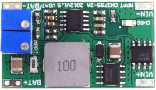
The CN3795 is a high-efficiency, step-down (buck) DC-DC converter designed for battery-powered applications. It is capable of converting a wide range of input voltages into a stable, adjustable output voltage, making it ideal for powering various electronic devices. The CN3795 is equipped with built-in protection features, including overcurrent protection and thermal shutdown, ensuring safe and reliable operation in demanding environments.
Explore Projects Built with CN3795

 Open Project in Cirkit Designer
 Open Project in Cirkit Designer
 Open Project in Cirkit Designer
 Open Project in Cirkit Designer
Explore Projects Built with CN3795

 Open Project in Cirkit Designer
 Open Project in Cirkit Designer
 Open Project in Cirkit Designer
 Open Project in Cirkit Designer
Common Applications
- Lithium-ion battery charging
- Solar-powered systems
- Portable electronic devices
- Industrial control systems
- LED drivers
Technical Specifications
Key Specifications
| Parameter | Value |
|---|---|
| Input Voltage Range | 4.5V to 28V |
| Output Voltage Range | Adjustable (up to 25V) |
| Maximum Output Current | 3A |
| Efficiency | Up to 95% |
| Switching Frequency | 300kHz |
| Operating Temperature | -40°C to +85°C |
| Protection Features | Overcurrent, thermal shutdown |
Pin Configuration and Descriptions
The CN3795 is typically available in an 8-pin SOP (Small Outline Package). Below is the pinout and description:
| Pin Number | Pin Name | Description |
|---|---|---|
| 1 | VIN | Input voltage pin. Connect to the power source (4.5V to 28V). |
| 2 | SW | Switching node. Connect to the inductor and diode. |
| 3 | GND | Ground pin. Connect to the system ground. |
| 4 | FB | Feedback pin. Used to set the output voltage via a resistor divider. |
| 5 | EN | Enable pin. Drive high to enable the converter, low to disable it. |
| 6 | COMP | Compensation pin. Connect a capacitor to stabilize the control loop. |
| 7 | VCC | Internal power supply pin. Connect a decoupling capacitor to ground. |
| 8 | NC | No connection. Leave this pin unconnected. |
Usage Instructions
How to Use the CN3795 in a Circuit
- Input Voltage: Connect the input voltage (4.5V to 28V) to the VIN pin. Ensure the input voltage is within the specified range.
- Output Voltage Adjustment: Use a resistor divider network connected to the FB pin to set the desired output voltage. The formula for the output voltage is: [ V_{OUT} = V_{REF} \times \left(1 + \frac{R1}{R2}\right) ] where ( V_{REF} ) is typically 1.25V.
- Inductor and Capacitor Selection: Choose an inductor and output capacitor based on the desired output current and voltage ripple. Refer to the datasheet for recommended values.
- Enable/Disable: Use the EN pin to enable or disable the converter. Pull the pin high (logic 1) to enable and low (logic 0) to disable.
- Compensation: Connect a capacitor to the COMP pin to stabilize the control loop. The value depends on the specific application and load conditions.
Important Considerations
- Thermal Management: Ensure adequate heat dissipation by using a proper PCB layout with thermal vias and copper planes.
- Input Capacitor: Place a low-ESR input capacitor close to the VIN pin to reduce input voltage ripple.
- Output Capacitor: Use a low-ESR output capacitor to minimize output voltage ripple and improve stability.
- Protection Features: The CN3795 includes overcurrent and thermal shutdown protection. Ensure the operating conditions do not exceed the specified limits.
Example: Using CN3795 with Arduino UNO
The CN3795 can be used to power an Arduino UNO by stepping down a higher input voltage (e.g., 12V) to 5V. Below is an example circuit and Arduino code to monitor the output voltage.
Circuit Setup
- Connect a 12V power source to the VIN pin of the CN3795.
- Set the output voltage to 5V using a resistor divider on the FB pin.
- Connect the output of the CN3795 to the 5V pin of the Arduino UNO.
- Use an analog input pin on the Arduino to monitor the output voltage.
Arduino Code
// CN3795 Output Voltage Monitoring with Arduino UNO
// This code reads the output voltage of the CN3795 using an analog pin
// and displays the voltage on the Serial Monitor.

const int voltagePin = A0; // Analog pin connected to CN3795 output
const float referenceVoltage = 5.0; // Arduino reference voltage (5V)
const int adcResolution = 1024; // 10-bit ADC resolution

void setup() {
  Serial.begin(9600); // Initialize Serial communication at 9600 baud
}

void loop() {
  int adcValue = analogRead(voltagePin); // Read the analog value
  // Calculate the output voltage based on the ADC value
  float outputVoltage = (adcValue * referenceVoltage) / adcResolution;

  // Print the output voltage to the Serial Monitor
  Serial.print("CN3795 Output Voltage: ");
  Serial.print(outputVoltage);
  Serial.println(" V");

  delay(1000); // Wait for 1 second before the next reading
}
Troubleshooting and FAQs
Common Issues and Solutions
No Output Voltage
- Cause: The EN pin is not pulled high.
- Solution: Ensure the EN pin is connected to a logic high signal or VIN through a resistor.
Excessive Heat
- Cause: Overloading or insufficient heat dissipation.
- Solution: Reduce the load current or improve thermal management with a better PCB layout.
Output Voltage Instability
- Cause: Incorrect compensation capacitor or poor layout.
- Solution: Use the recommended compensation capacitor value and follow proper PCB layout guidelines.
High Output Ripple
- Cause: Inadequate output capacitor or poor capacitor quality.
- Solution: Use a low-ESR capacitor with the recommended capacitance value.
FAQs
Q1: Can the CN3795 be used for charging batteries?
Yes, the CN3795 is suitable for charging batteries, including lithium-ion batteries, by configuring the output voltage and current appropriately.
Q2: What is the maximum input voltage for the CN3795?
The maximum input voltage is 28V. Exceeding this value may damage the component.
Q3: How do I calculate the resistor values for the feedback network?
Use the formula ( V_{OUT} = V_{REF} \times \left(1 + \frac{R1}{R2}\right) ), where ( V_{REF} ) is 1.25V. Select ( R1 ) and ( R2 ) to achieve the desired output voltage.
Q4: Can the CN3795 operate without a load?
Yes, the CN3795 can operate without a load, but ensure the output voltage remains stable under no-load conditions.