How to Use Heart Bioamp Candy: Examples, Pinouts, and Specs
Introduction
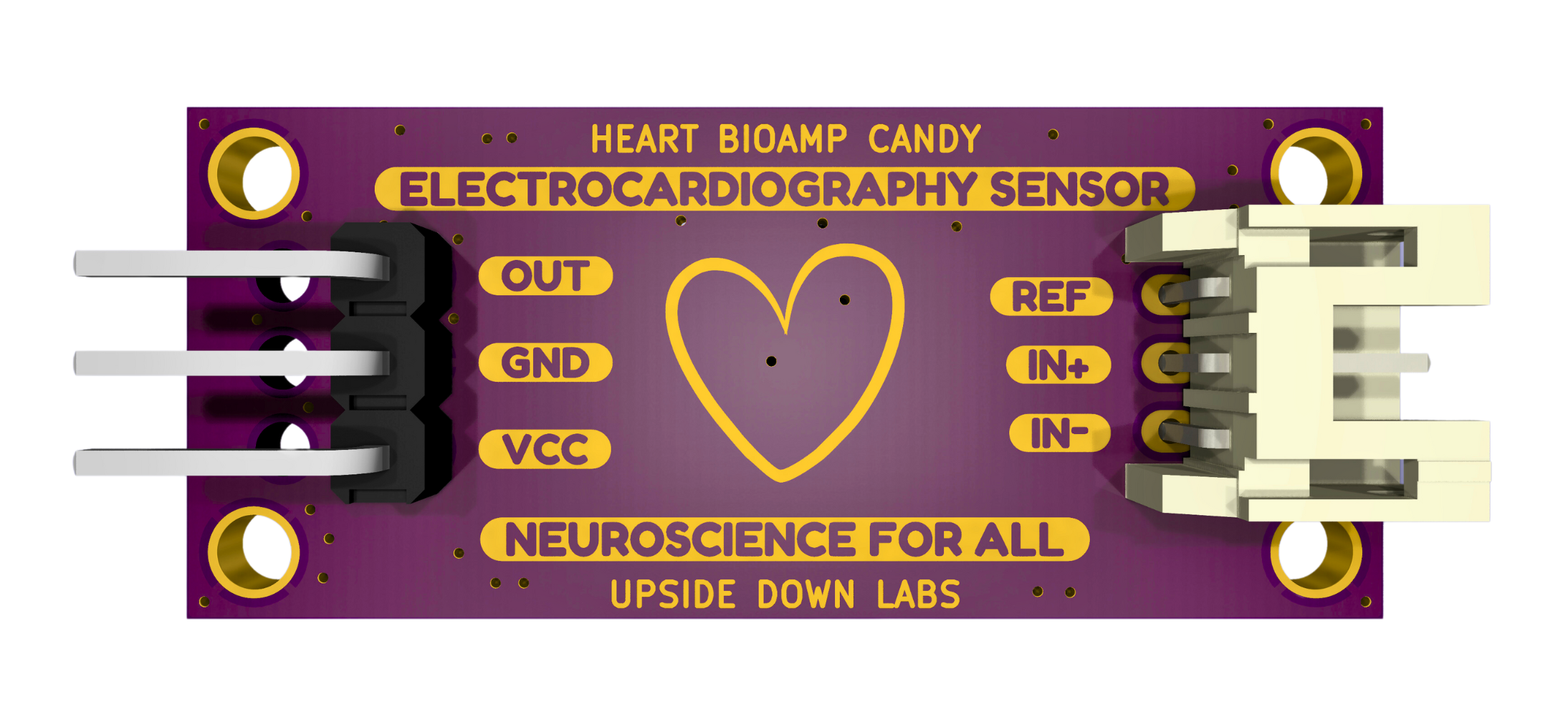
The Heart Bioamp Candy by Upside Down Labs is a compact and efficient bioamplifier designed for wearable health monitoring applications. It is capable of amplifying and processing bioelectrical signals from the heart, such as ECG (Electrocardiogram) signals, to provide accurate data for analysis. This component is ideal for developers and researchers working on health monitoring systems, fitness trackers, and biomedical projects.
Explore Projects Built with Heart Bioamp Candy
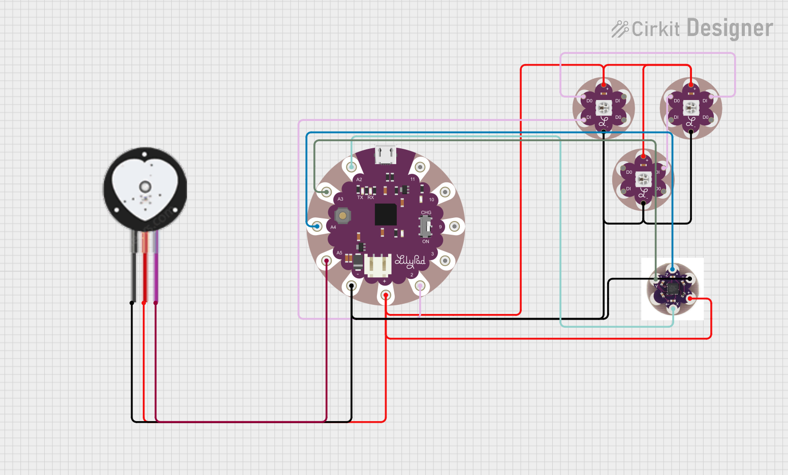
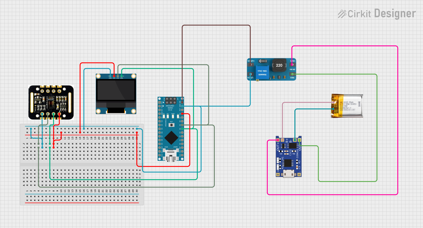
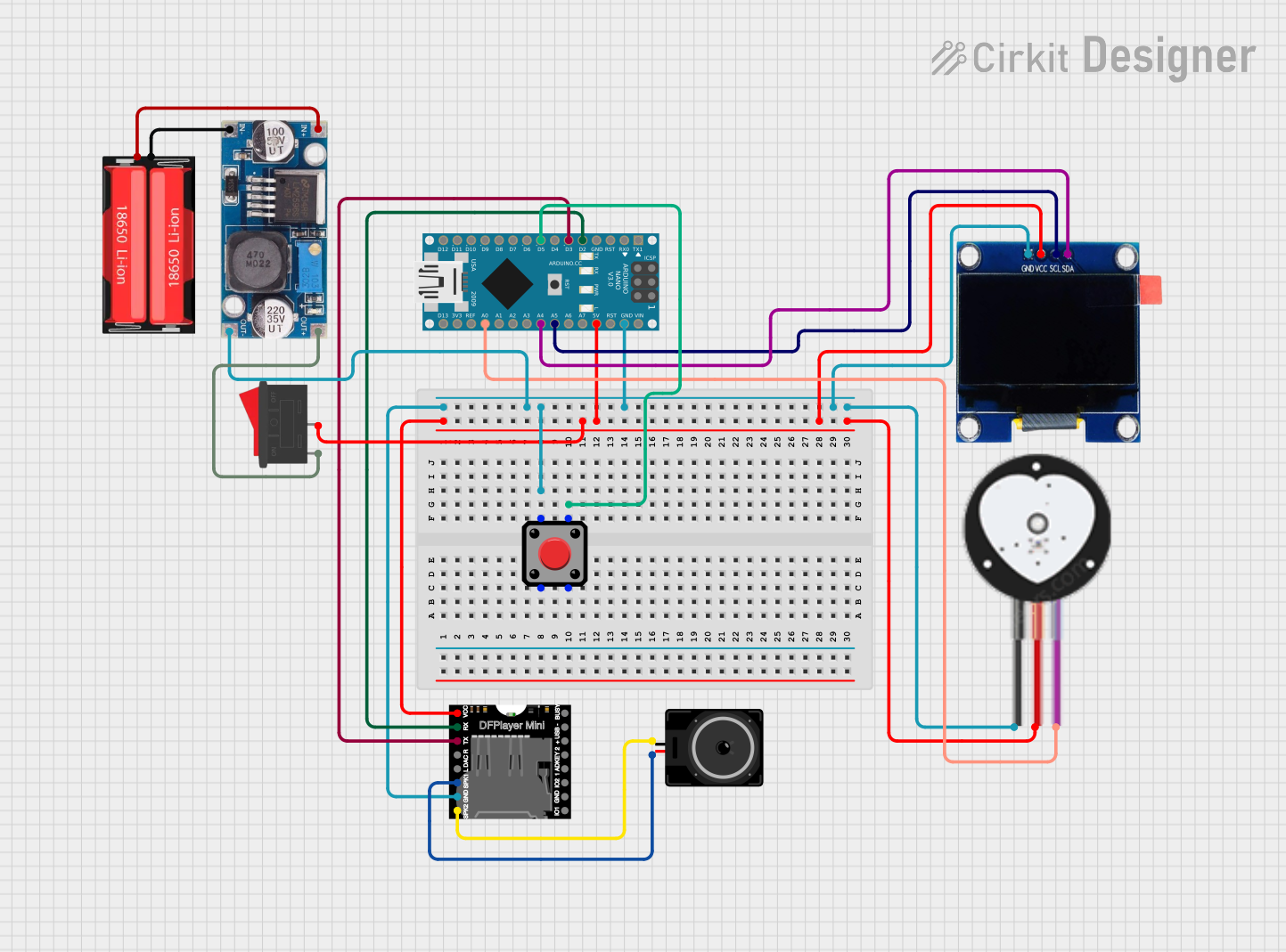
Explore Projects Built with Heart Bioamp Candy
Common Applications and Use Cases
- Wearable health monitoring devices
- ECG signal acquisition and analysis
- Fitness trackers and heart rate monitors
- Biomedical research and prototyping
- Educational projects in bioelectronics
Technical Specifications
The Heart Bioamp Candy is designed to provide high-quality signal amplification while maintaining a compact form factor. Below are its key technical specifications:
General Specifications
| Parameter | Value |
|---|---|
| Supply Voltage | 3.3V to 5V |
| Input Signal Range | ±5mV |
| Gain | 1000x |
| Bandwidth | 0.5Hz to 50Hz |
| Output Voltage Range | 0V to Vcc |
| Power Consumption | < 10mA |
| Dimensions | 20mm x 20mm |
Pin Configuration and Descriptions
| Pin Name | Type | Description |
|---|---|---|
| VCC | Power | Power supply input (3.3V to 5V). |
| GND | Ground | Ground connection. |
| IN+ | Input | Positive input for bioelectrical signal (e.g., electrode connection). |
| IN- | Input | Negative input for bioelectrical signal (e.g., electrode connection). |
| OUT | Output | Amplified bioelectrical signal output. |
Usage Instructions
The Heart Bioamp Candy is straightforward to use in a circuit. Follow the steps below to integrate it into your project:
Connecting the Component
- Power Supply: Connect the
VCCpin to a 3.3V or 5V power source and theGNDpin to the ground of your circuit. - Signal Input: Attach the
IN+andIN-pins to the electrodes or signal source. Ensure proper placement of electrodes for accurate signal acquisition. - Signal Output: Connect the
OUTpin to an ADC (Analog-to-Digital Converter) pin of a microcontroller or an oscilloscope for signal monitoring.
Important Considerations
- Electrode Placement: Proper placement of electrodes on the body is critical for accurate signal acquisition. Ensure good skin contact and use conductive gel if necessary.
- Noise Reduction: Minimize noise by using shielded cables and keeping the component away from high-frequency noise sources.
- Power Supply Stability: Use a stable and clean power supply to avoid introducing noise into the signal.
Example: Using with Arduino UNO
The Heart Bioamp Candy can be easily interfaced with an Arduino UNO for ECG signal monitoring. Below is an example code snippet:
// Example code for interfacing Heart Bioamp Candy with Arduino UNO
// Reads the amplified ECG signal and prints it to the Serial Monitor

const int bioampPin = A0; // Connect the OUT pin of Heart Bioamp Candy to A0

void setup() {
  Serial.begin(9600); // Initialize serial communication at 9600 baud
  pinMode(bioampPin, INPUT); // Set the bioamp pin as input
}

void loop() {
  int signal = analogRead(bioampPin); // Read the amplified signal
  Serial.println(signal); // Print the signal value to the Serial Monitor
  delay(10); // Small delay for stable readings
}
Best Practices
- Use a low-pass filter in your circuit if additional noise filtering is required.
- Avoid touching the electrodes or wires during operation to prevent signal distortion.
- Ensure the component is securely mounted to avoid mechanical stress.
Troubleshooting and FAQs
Common Issues and Solutions
No Signal Output
- Cause: Incorrect electrode placement or poor contact.
- Solution: Reposition the electrodes and ensure good skin contact. Use conductive gel if needed.
High Noise in Output Signal
- Cause: Electromagnetic interference or unstable power supply.
- Solution: Use shielded cables, keep the component away from noise sources, and ensure a clean power supply.
Output Signal Saturation
- Cause: Input signal exceeds the amplifier's range.
- Solution: Check the input signal range and ensure it is within ±5mV.
Component Overheating
- Cause: Excessive power supply voltage.
- Solution: Ensure the supply voltage is within the specified range (3.3V to 5V).
FAQs
Q1: Can the Heart Bioamp Candy be used for EMG or EEG signals?
A1: While it is optimized for ECG signals, it can also be used for EMG or EEG signals with proper electrode placement and signal conditioning.
Q2: What type of electrodes should I use?
A2: Standard Ag/AgCl electrodes are recommended for best results.
Q3: Can I use this component with a 3.3V microcontroller?
A3: Yes, the Heart Bioamp Candy is compatible with both 3.3V and 5V systems.
Q4: How do I visualize the output signal?
A4: You can use an oscilloscope or plot the signal using a microcontroller and a serial plotter.
By following this documentation, you can effectively integrate the Heart Bioamp Candy into your projects and achieve reliable bioelectrical signal monitoring.