How to Use PNP Transistor (CBE): Examples, Pinouts, and Specs

Introduction
A PNP transistor is a type of bipolar junction transistor (BJT) characterized by its three terminals: Collector (C), Base (B), and Emitter (E). Unlike its NPN counterpart, the PNP transistor is designed such that the majority charge carriers are holes, making it suitable for use in positive ground configurations. PNP transistors are commonly used in electronic circuits for amplification, switching applications, and as part of more complex integrated circuits.
Explore Projects Built with PNP Transistor (CBE)
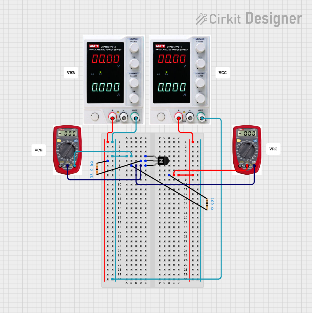


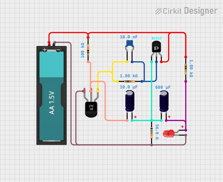
Explore Projects Built with PNP Transistor (CBE)
Common Applications and Use Cases
- Signal Amplification
- Switching Loads
- Audio Amplifiers
- Voltage Regulation
- Inverter Circuits
Technical Specifications
Key Technical Details
- Maximum Collector-Emitter Voltage (Vce): The maximum voltage that can be applied across the collector-emitter terminals without causing damage.
- Maximum Collector Current (Ic): The maximum current that can flow through the collector terminal.
- Power Dissipation (Pd): The maximum power the transistor can dissipate without damage.
- Gain (hFE): The current gain, which is the ratio of collector current to base current.
Pin Configuration and Descriptions
| Pin Number | Name | Description |
|---|---|---|
| 1 | Emitter | Emits charge carriers, holes in this case. |
| 2 | Base | Controls the transistor's operation. |
| 3 | Collector | Collects charge carriers from the emitter. |
Usage Instructions
How to Use the Component in a Circuit
- Biasing the Transistor: To turn on a PNP transistor, ensure the base is at a lower potential than the emitter.
- Base Resistor: Always use a base resistor to limit the base current and prevent damage to the transistor.
- Load Placement: In a switching circuit, the load is typically connected to the collector and the positive supply voltage.
- Emitter to Positive Voltage: The emitter is usually connected to the positive side of the power supply.
Important Considerations and Best Practices
- Saturation: Ensure the transistor is fully saturated for use as a switch to minimize voltage drop across the collector-emitter terminals.
- Heat Sinking: For high-power applications, use a heat sink to prevent overheating.
- Current Limiting: Always design the circuit to keep the current within the maximum collector current rating.
Example Circuit: PNP Transistor as a Switch
// Code to control a PNP transistor connected to an Arduino UNO
const int basePin = 3; // Connect to the base of the PNP transistor through a resistor

void setup() {
  pinMode(basePin, OUTPUT);
}

void loop() {
  digitalWrite(basePin, LOW); // Turns the PNP transistor ON
  delay(1000);               // Wait for 1 second
  digitalWrite(basePin, HIGH); // Turns the PNP transistor OFF
  delay(1000);                // Wait for 1 second
}
Note: The above code assumes that the emitter of the PNP transistor is connected to the positive voltage supply and the collector is connected to the load which is then connected to ground.
Troubleshooting and FAQs
Common Issues Users Might Face
- Transistor Not Switching: Check if the base is sufficiently negative relative to the emitter.
- Excessive Heat: Ensure the power dissipation is within the transistor's limits.
- Unexpected Voltage Drops: Verify that the transistor is fully saturated when used as a switch.
Solutions and Tips for Troubleshooting
- Base Voltage: Adjust the base resistor value to achieve the desired base current.
- Heat Sinking: Attach a heat sink if the transistor is getting too hot during operation.
- Check Connections: Ensure all connections are secure and the transistor is not installed backward.
FAQs
Q: Can I use a PNP transistor in place of an NPN transistor? A: While both are BJTs, they operate differently. A PNP transistor requires a different biasing scheme and is not a direct replacement for an NPN transistor.
Q: How do I choose the correct base resistor value? A: The base resistor value can be calculated using Ohm's law, taking into account the desired base current and the voltage difference between the base and emitter.
Q: What happens if I reverse the collector and emitter? A: The transistor will not function properly as the collector and emitter are doped differently and are not interchangeable.
Q: Why is my PNP transistor not turning off? A: Ensure that the base is sufficiently positive relative to the emitter to turn off the transistor. Also, check for any leakage currents or incorrect connections.