How to Use KINOCY: Examples, Pinouts, and Specs
Introduction
KINOCY, manufactured by MUKTI, is a brand renowned for its high-quality electronic components, including sensors, controllers, and other circuit elements. The KC868-A16 is a versatile and reliable component designed for use in automation, robotics, and other electronic systems requiring precise control and monitoring. Its robust design and ease of integration make it a popular choice for both hobbyists and professionals.
Explore Projects Built with KINOCY

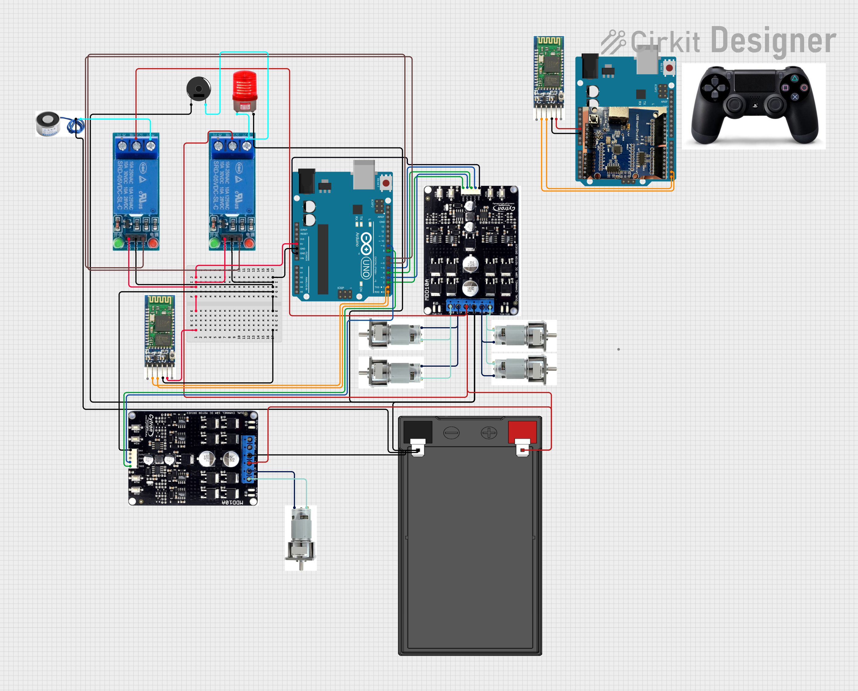
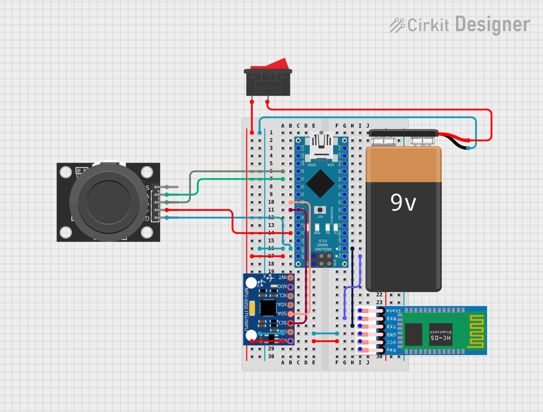
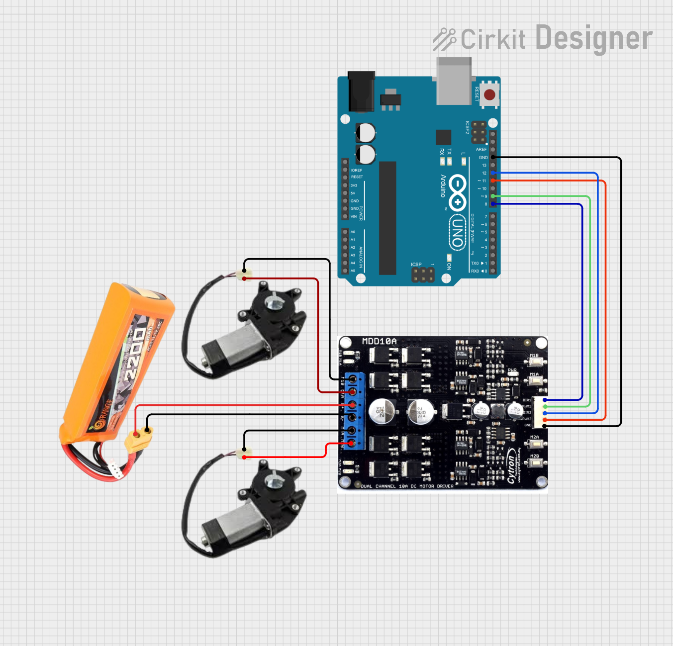
Explore Projects Built with KINOCY
Common Applications and Use Cases
- Home automation systems
- Industrial control systems
- Robotics and mechatronics
- IoT (Internet of Things) devices
- Smart appliances and energy management systems
Technical Specifications
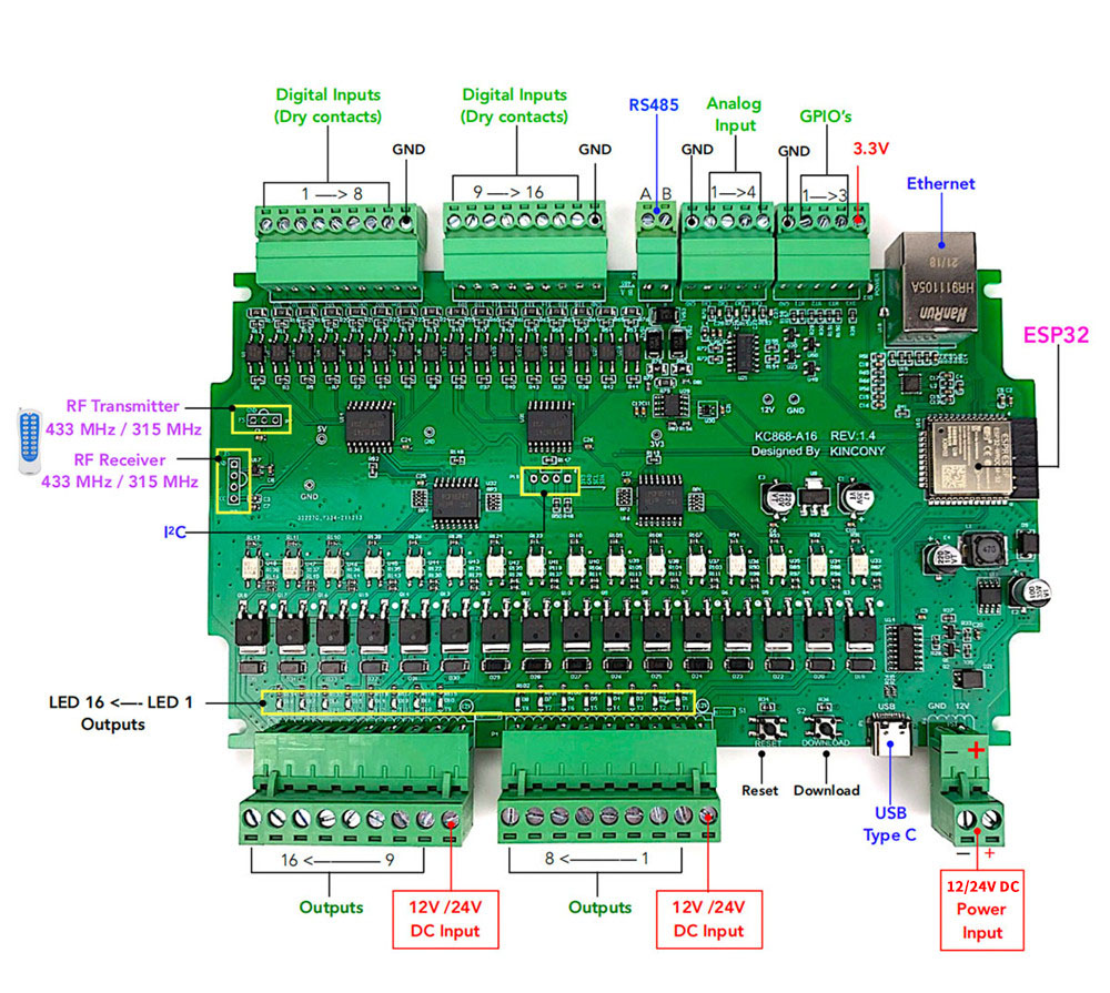
The KC868-A16 is a 16-channel relay controller with advanced features for seamless integration into various electronic systems. Below are its key technical details:
Key Technical Details
- Operating Voltage: 12V DC
- Relay Channels: 16
- Relay Type: SPDT (Single Pole Double Throw)
- Maximum Load per Channel: 10A at 250V AC or 10A at 30V DC
- Communication Interface: RS232, RS485, and Ethernet
- Control Protocols: Modbus RTU, TCP/IP
- Operating Temperature Range: -20°C to 70°C
- Dimensions: 200mm x 120mm x 40mm
- Power Consumption: < 2W (idle state)
Pin Configuration and Descriptions
The KC868-A16 features a terminal block for relay outputs and communication ports for interfacing. Below is the pin configuration:
Relay Output Terminal Block
| Pin Number | Description |
|---|---|
| 1-16 | Relay output channels 1-16 |
| COM | Common terminal for relays |
| NC | Normally Closed terminal |
| NO | Normally Open terminal |
Communication Ports
| Port Type | Pin Description |
|---|---|
| RS232 | TX (Transmit), RX (Receive), GND |
| RS485 | A (Data+), B (Data-), GND |
| Ethernet | RJ45 connector for TCP/IP communication |
Usage Instructions
The KC868-A16 is designed for easy integration into automation and control systems. Follow the steps below to use the component effectively:
Connecting the KC868-A16
- Power Supply: Connect a 12V DC power supply to the power input terminals.
- Relay Outputs: Wire the devices you want to control (e.g., lights, motors) to the relay output terminals. Use the NO (Normally Open) or NC (Normally Closed) terminals based on your application.
- Communication Interface: Choose the appropriate communication interface (RS232, RS485, or Ethernet) and connect it to your controller or PC.
Controlling the Relays
The KC868-A16 supports Modbus RTU and TCP/IP protocols for relay control. Below is an example of controlling the relays using an Arduino UNO via RS485:
Arduino UNO Example Code
#include <ModbusMaster.h>

// Create an instance of the ModbusMaster library
ModbusMaster node;

// Define the RS485 control pin
#define RS485_CONTROL_PIN 2

void preTransmission() {
  digitalWrite(RS485_CONTROL_PIN, HIGH); // Enable RS485 transmission
}

void postTransmission() {
  digitalWrite(RS485_CONTROL_PIN, LOW);  // Disable RS485 transmission
}

void setup() {
  pinMode(RS485_CONTROL_PIN, OUTPUT);
  digitalWrite(RS485_CONTROL_PIN, LOW);

  // Initialize Modbus communication
  Serial.begin(9600); // Set baud rate for RS485
  node.begin(1, Serial); // Set Modbus slave ID to 1
  node.preTransmission(preTransmission);
  node.postTransmission(postTransmission);
}

void loop() {
  // Turn on relay 1
  uint8_t result = node.writeSingleCoil(0, 1); // Relay 1 is coil 0
  delay(1000); // Wait for 1 second

  // Turn off relay 1
  result = node.writeSingleCoil(0, 0);
  delay(1000); // Wait for 1 second
}
Important Considerations and Best Practices
- Ensure the total load on each relay does not exceed the specified maximum (10A at 250V AC or 30V DC).
- Use appropriate snubber circuits or flyback diodes when switching inductive loads to protect the relays.
- Verify the communication settings (baud rate, slave ID, etc.) match your controller's configuration.
- Avoid exposing the component to extreme temperatures or humidity.
Troubleshooting and FAQs
Common Issues and Solutions
Relays not responding:
- Verify the power supply is connected and providing 12V DC.
- Check the communication interface connections and settings.
- Ensure the relay control commands are sent correctly.
Communication failure:
- Confirm the baud rate and protocol settings match between the KC868-A16 and the controller.
- Check the RS485 or Ethernet cable connections for faults.
Relays stuck in one state:
- Inspect the connected load for short circuits or excessive current draw.
- Replace the relay if it is damaged due to overloading.
FAQs
Q: Can I use the KC868-A16 with a Raspberry Pi?
A: Yes, the KC868-A16 can be controlled using a Raspberry Pi via RS485 or Ethernet. Use libraries like pymodbus for Modbus communication.
Q: What is the maximum cable length for RS485 communication?
A: RS485 supports cable lengths up to 1200 meters, but ensure proper termination resistors are used.
Q: Can I control the relays manually without a controller?
A: Yes, you can manually toggle the relays using the onboard test buttons (if available) or by applying control signals directly.
This concludes the documentation for the KINOCY KC868-A16. For further assistance, refer to the manufacturer's datasheet or contact MUKTI support.