How to Use BNO055: Examples, Pinouts, and Specs
Introduction
The BNO055 is a 9-axis absolute orientation sensor that integrates a 3-axis accelerometer, a 3-axis gyroscope, and a 3-axis magnetometer into a single package. Unlike traditional sensors, the BNO055 features an onboard microcontroller that fuses raw sensor data to provide accurate orientation information in the form of Euler angles (pitch, roll, yaw) or quaternions. This eliminates the need for complex sensor fusion algorithms on the host microcontroller.
Explore Projects Built with BNO055
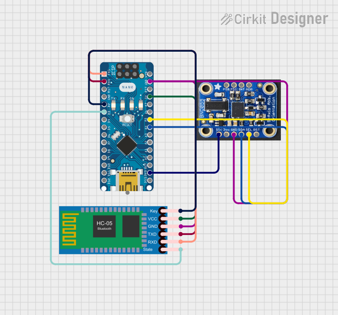
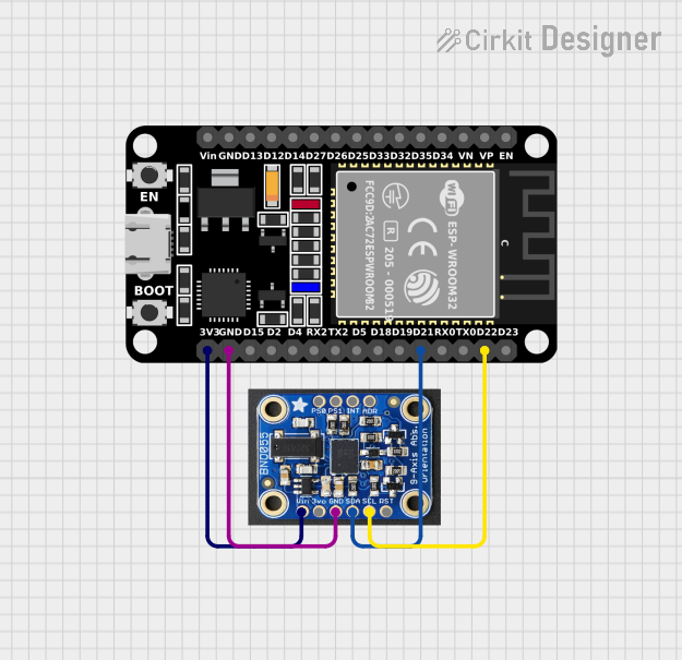

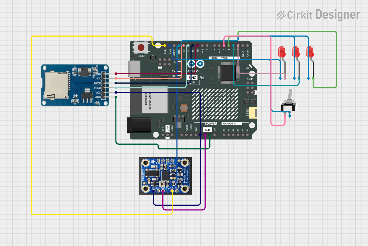
Explore Projects Built with BNO055
Common Applications and Use Cases
- Robotics for precise motion tracking and navigation
- Drones for stable flight and orientation control
- Wearable devices for activity recognition and gesture detection
- Virtual reality (VR) and augmented reality (AR) systems
- Industrial automation and human-machine interfaces
Technical Specifications
The BNO055 is a highly versatile sensor with the following key specifications:
| Parameter | Value |
|---|---|
| Operating Voltage | 2.4V to 3.6V |
| Communication Interfaces | I²C (default address: 0x28 or 0x29), UART |
| Power Consumption | 12 mA (typical in normal mode) |
| Operating Temperature Range | -40°C to +85°C |
| Accelerometer Range | ±2g, ±4g, ±8g, ±16g |
| Gyroscope Range | ±125°/s, ±250°/s, ±500°/s, ±1000°/s, ±2000°/s |
| Magnetometer Range | ±1300 µT |
| Output Data Formats | Euler angles, quaternions, linear acceleration, gravity vector |
| Dimensions | 3.8 mm x 5.2 mm x 1.1 mm |
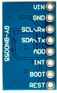
Pin Configuration and Descriptions
The BNO055 is typically available in a 14-pin package. Below is the pinout description:
| Pin | Name | Description |
|---|---|---|
| 1 | GND | Ground connection |
| 2 | VDD | Power supply (2.4V to 3.6V) |
| 3 | VDDIO | I/O voltage level (typically connected to VDD) |
| 4 | PS0 | Protocol selection pin 0 (used to select I²C or UART mode) |
| 5 | PS1 | Protocol selection pin 1 (used to select I²C or UART mode) |
| 6 | COM3 | Reserved for future use (leave unconnected) |
| 7 | RSTN | Active-low reset pin |
| 8 | INT | Interrupt output (can be configured for various events) |
| 9 | SCL | I²C clock line |
| 10 | SDA | I²C data line |
| 11 | BOOTN | Active-low bootloader mode pin |
| 12 | TXD | UART transmit data (used in UART mode) |
| 13 | RXD | UART receive data (used in UART mode) |
| 14 | NC | Not connected (leave unconnected) |
Usage Instructions
How to Use the BNO055 in a Circuit
- Power Supply: Connect the VDD and VDDIO pins to a 3.3V power source. Ensure the GND pin is connected to the ground of your circuit.
- Communication Interface:
- For I²C communication, connect the SDA and SCL pins to the corresponding pins on your microcontroller. Pull-up resistors (typically 4.7 kΩ) are required on both lines.
- For UART communication, connect the TXD and RXD pins to the UART pins of your microcontroller.
- Protocol Selection: Use the PS0 and PS1 pins to select the communication protocol:
- I²C mode: PS0 = 0, PS1 = 1
- UART mode: PS0 = 1, PS1 = 0
- Interrupts: Optionally, connect the INT pin to your microcontroller to handle events like data ready or orientation changes.
- Reset: Connect the RSTN pin to a GPIO pin on your microcontroller for manual resets, or pull it high for normal operation.
Important Considerations and Best Practices
- Calibration: The BNO055 requires calibration for accurate results. Follow the calibration procedure outlined in the datasheet to calibrate the accelerometer, gyroscope, and magnetometer.
- Mounting Orientation: Ensure the sensor is mounted securely and aligned with your system's coordinate axes.
- Power Supply Noise: Use decoupling capacitors (e.g., 0.1 µF) near the VDD pin to reduce power supply noise.
- I²C Address: The default I²C address is 0x28. If multiple BNO055 sensors are used, the address can be changed to 0x29 by pulling the COM3 pin high.
Example Code for Arduino UNO
Below is an example of how to interface the BNO055 with an Arduino UNO using I²C:
#include <Wire.h>
#include <Adafruit_Sensor.h>
#include <Adafruit_BNO055.h>

// Create an instance of the BNO055 sensor
Adafruit_BNO055 bno = Adafruit_BNO055(55);

void setup() {
  Serial.begin(9600); // Initialize serial communication
  while (!Serial);    // Wait for the serial monitor to open

  // Initialize the BNO055 sensor
  if (!bno.begin()) {
    Serial.println("Error: BNO055 not detected. Check connections.");
    while (1);
  }

  // Set the sensor to NDOF mode (fusion mode for orientation data)
  bno.setMode(Adafruit_BNO055::OPERATION_MODE_NDOF);

  Serial.println("BNO055 initialized successfully!");
}

void loop() {
  // Get orientation data (Euler angles)
  sensors_event_t event;
  bno.getEvent(&event);

  // Print pitch, roll, and yaw to the serial monitor
  Serial.print("Pitch: ");
  Serial.print(event.orientation.x);
  Serial.print(" Roll: ");
  Serial.print(event.orientation.y);
  Serial.print(" Yaw: ");
  Serial.println(event.orientation.z);

  delay(100); // Delay for readability
}
Troubleshooting and FAQs
Common Issues and Solutions
Sensor Not Detected:
- Ensure the I²C connections (SDA, SCL) are correct and have pull-up resistors.
- Verify the I²C address (default is 0x28). If using 0x29, ensure COM3 is pulled high.
- Check the power supply voltage (2.4V to 3.6V).
Incorrect Orientation Data:
- Perform a full calibration of the accelerometer, gyroscope, and magnetometer.
- Ensure the sensor is mounted securely and aligned with the system's axes.
No Data Output:
- Verify that the sensor is in the correct operating mode (e.g., NDOF for orientation data).
- Check the RSTN pin to ensure the sensor is not in reset mode.
FAQs
Q: Can the BNO055 operate at 5V?
A: No, the BNO055 operates at a maximum voltage of 3.6V. Use a level shifter if interfacing with a 5V system.Q: How do I know if the sensor is calibrated?
A: The BNO055 provides calibration status registers. Refer to the datasheet or library documentation to read these values.Q: Can I use the BNO055 with SPI?
A: No, the BNO055 supports only I²C and UART communication protocols.Q: What is the maximum update rate of the sensor?
A: The BNO055 can output data at up to 100 Hz in fusion mode.
This concludes the documentation for the BNO055. For further details, refer to the official datasheet and application notes.