How to Use Raspberry pi zero 2w: Examples, Pinouts, and Specs
Introduction
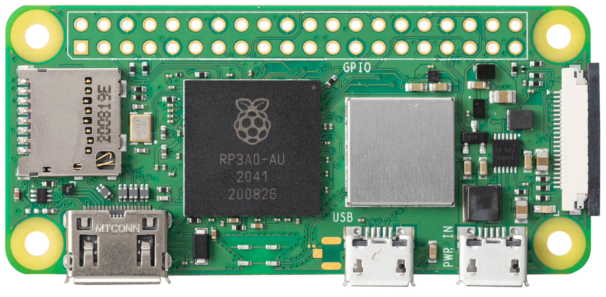
The Raspberry Pi Zero 2 W is a compact, low-cost single-board computer designed for a wide range of applications. It features a quad-core ARM Cortex-A53 processor, wireless connectivity (Wi-Fi and Bluetooth), and a 40-pin GPIO header for interfacing with various electronic components. Its small form factor and affordable price make it an excellent choice for DIY projects, IoT devices, and embedded systems.
Explore Projects Built with Raspberry pi zero 2w
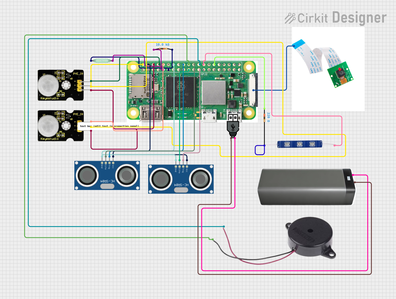
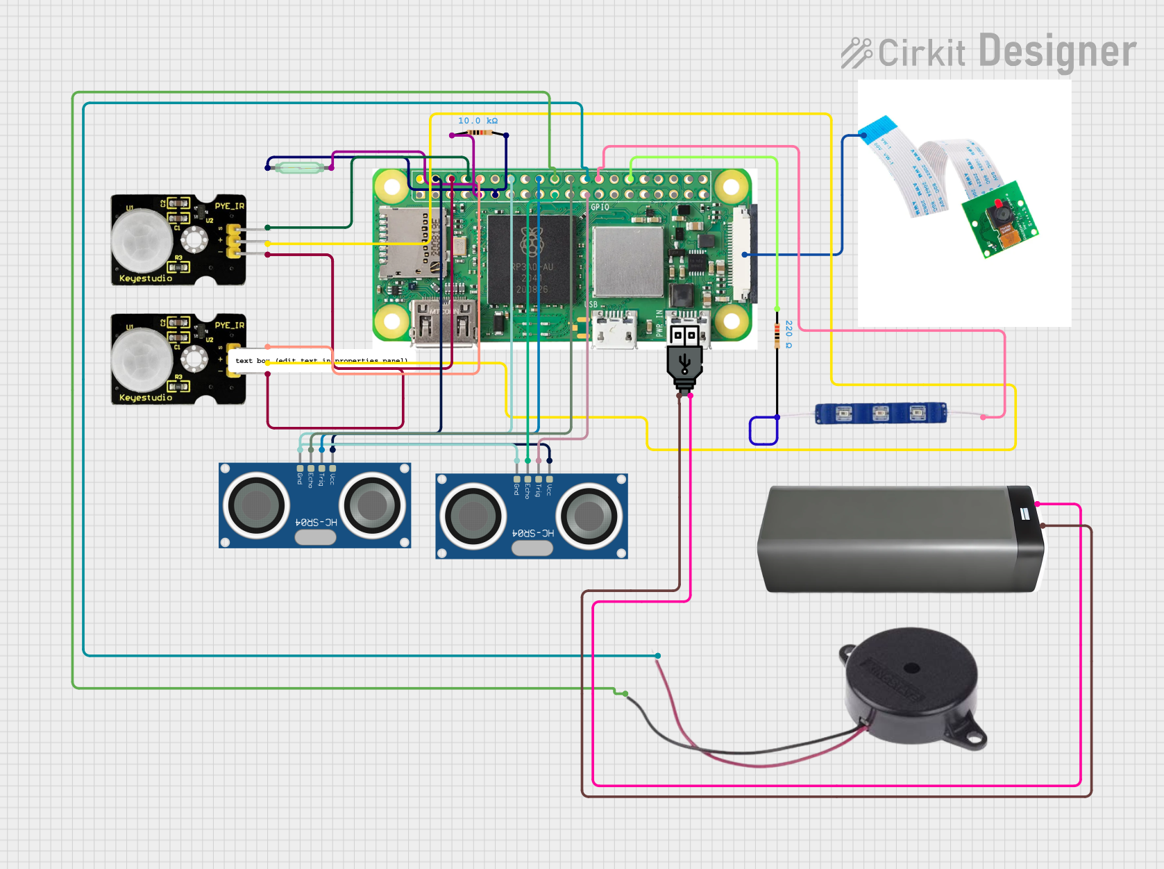

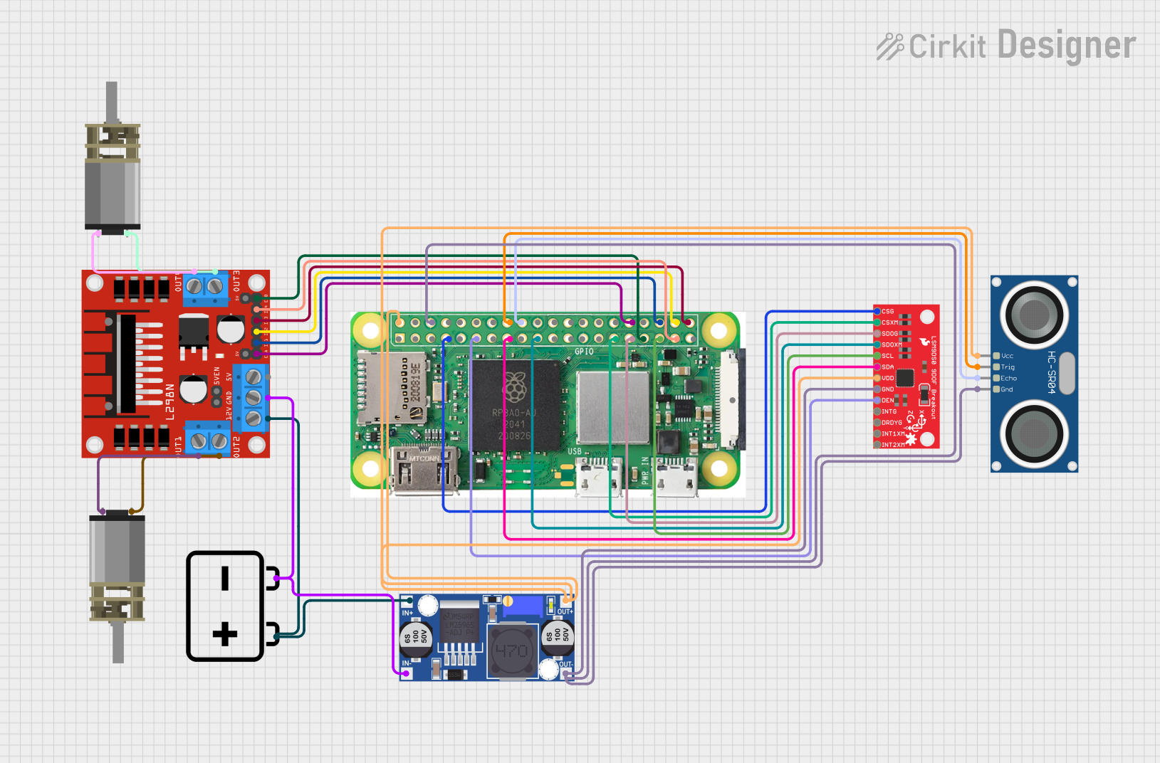
Explore Projects Built with Raspberry pi zero 2w
Common Applications and Use Cases
- Home automation systems
- IoT (Internet of Things) devices
- Media streaming and playback
- Robotics and motor control
- Prototyping and educational projects
- Retro gaming consoles
- Networked sensors and data loggers
Technical Specifications
Key Technical Details
- Processor: Broadcom BCM2710A1, quad-core ARM Cortex-A53 @ 1 GHz
- RAM: 512 MB LPDDR2
- Wireless Connectivity:
- Wi-Fi: 802.11 b/g/n (2.4 GHz)
- Bluetooth: 4.2, BLE
- GPIO: 40-pin header (unpopulated)
- Video Output: Mini HDMI (1080p at 30 fps)
- USB Ports:
- 1x Micro-USB for power
- 1x Micro-USB OTG for peripherals
- Storage: MicroSD card slot
- Power Supply: 5V/2.5A via Micro-USB
- Dimensions: 65mm x 30mm x 5mm
- Weight: Approximately 9g
Pin Configuration and Descriptions
The Raspberry Pi Zero 2 W features a 40-pin GPIO header. Below is a table summarizing the pin configuration:
| Pin Number | Pin Name | Function | Description |
|---|---|---|---|
| 1 | 3.3V | Power | 3.3V power supply |
| 2 | 5V | Power | 5V power supply |
| 3 | GPIO2 (SDA1) | I2C Data | Data line for I2C communication |
| 4 | 5V | Power | 5V power supply |
| 5 | GPIO3 (SCL1) | I2C Clock | Clock line for I2C communication |
| 6 | GND | Ground | Ground connection |
| 7 | GPIO4 | General Purpose I/O | Configurable GPIO pin |
| 8 | GPIO14 (TXD) | UART Transmit | Serial communication TX |
| 9 | GND | Ground | Ground connection |
| 10 | GPIO15 (RXD) | UART Receive | Serial communication RX |
| ... | ... | ... | ... |
For the full GPIO pinout, refer to the official Raspberry Pi documentation.
Usage Instructions
How to Use the Raspberry Pi Zero 2 W in a Circuit
- Powering the Board: Connect a 5V/2.5A power supply to the Micro-USB power port.
- Connecting Peripherals: Use the Micro-USB OTG port to connect peripherals like a keyboard, mouse, or USB hub. For video output, connect a monitor via the Mini HDMI port.
- Booting the System: Insert a microSD card with a pre-installed Raspberry Pi OS (or other compatible OS) into the microSD card slot. Power on the board, and it will boot from the microSD card.
- Using GPIO Pins: Connect sensors, actuators, or other components to the GPIO pins. Use Python or other programming languages to control the GPIO pins.
Important Considerations and Best Practices
- Power Supply: Always use a reliable 5V/2.5A power supply to ensure stable operation.
- Static Protection: Handle the board with care to avoid static discharge, which can damage the components.
- GPIO Voltage Levels: The GPIO pins operate at 3.3V logic levels. Do not connect 5V signals directly to the GPIO pins.
- Cooling: For intensive tasks, consider adding a heatsink to prevent overheating.
Example: Blinking an LED with GPIO
Below is an example of how to blink an LED connected to GPIO17 (pin 11) using Python:
Import the GPIO library
import RPi.GPIO as GPIO import time
Set up GPIO mode
GPIO.setmode(GPIO.BCM) # Use Broadcom pin numbering GPIO.setwarnings(False)
Define the GPIO pin for the LED
LED_PIN = 17
Set up the LED pin as an output
GPIO.setup(LED_PIN, GPIO.OUT)
Blink the LED in a loop
try: while True: GPIO.output(LED_PIN, GPIO.HIGH) # Turn on the LED time.sleep(1) # Wait for 1 second GPIO.output(LED_PIN, GPIO.LOW) # Turn off the LED time.sleep(1) # Wait for 1 second except KeyboardInterrupt: # Clean up GPIO settings on exit GPIO.cleanup()
Troubleshooting and FAQs
Common Issues and Solutions
The board does not boot:
- Ensure the microSD card is properly inserted and contains a valid OS image.
- Verify the power supply provides sufficient current (5V/2.5A).
- Check the HDMI connection if no display output is visible.
Wi-Fi or Bluetooth is not working:
- Ensure the correct drivers are installed in the OS.
- Verify that the wireless network credentials are correctly configured.
GPIO pins are not responding:
- Double-check the pin numbering (BCM vs. physical pin numbers).
- Ensure the GPIO pins are configured correctly in your code.
Overheating:
- If the board gets too hot, consider adding a heatsink or improving ventilation.
FAQs
Can I power the Raspberry Pi Zero 2 W via GPIO pins? Yes, you can power the board by supplying 5V to the 5V pin and connecting GND to a ground pin. However, this bypasses the onboard power protection circuitry, so proceed with caution.
What operating systems are compatible with the Raspberry Pi Zero 2 W? The board supports Raspberry Pi OS, Ubuntu, and other Linux-based distributions designed for ARM processors.
Can I use the Raspberry Pi Zero 2 W for AI/ML projects? While the board is not as powerful as other Raspberry Pi models, it can handle lightweight AI/ML tasks using frameworks like TensorFlow Lite.
How do I enable SSH for headless setup? Create an empty file named
ssh(without any extension) in the boot partition of the microSD card before inserting it into the board. This will enable SSH on boot.
By following this documentation, you can effectively use the Raspberry Pi Zero 2 W for a variety of projects and applications.