How to Use Adafruit QT Py: Examples, Pinouts, and Specs
Introduction
The Adafruit QT Py is a compact, versatile development board based on the Microchip SAMD21E18 ARM Cortex-M0+ microcontroller. It is designed for ease of use and flexibility, featuring a USB-C connector for programming and power, a built-in RGB NeoPixel LED, and a variety of GPIO pins. The QT Py is compatible with CircuitPython and Arduino IDE, which allows it to be used in a wide range of projects, from simple LED controls to more complex IoT applications.
Explore Projects Built with Adafruit QT Py


Explore Projects Built with Adafruit QT Py
Common Applications and Use Cases
- Wearable electronics
- IoT devices
- Prototyping and educational projects
- USB interface for sensors and peripherals
- Custom keyboard development
- Light and sound interactive projects
Technical Specifications
Key Technical Details
- Microcontroller: Microchip SAMD21E18 ARM Cortex-M0+
- Operating Voltage: 3.3V
- Input Voltage (recommended): 5V via USB-C
- Digital I/O Pins: 11, with 4 PWM channels
- Analog Input Pins: 1 (10-bit ADC)
- Flash Memory: 256 KB
- SRAM: 32 KB
- Clock Speed: 48 MHz
- LED: 1 x RGB NeoPixel
- Interfaces: I2C, SPI, UART
- Dimensions: 21.0mm x 17.8mm x 4.0mm
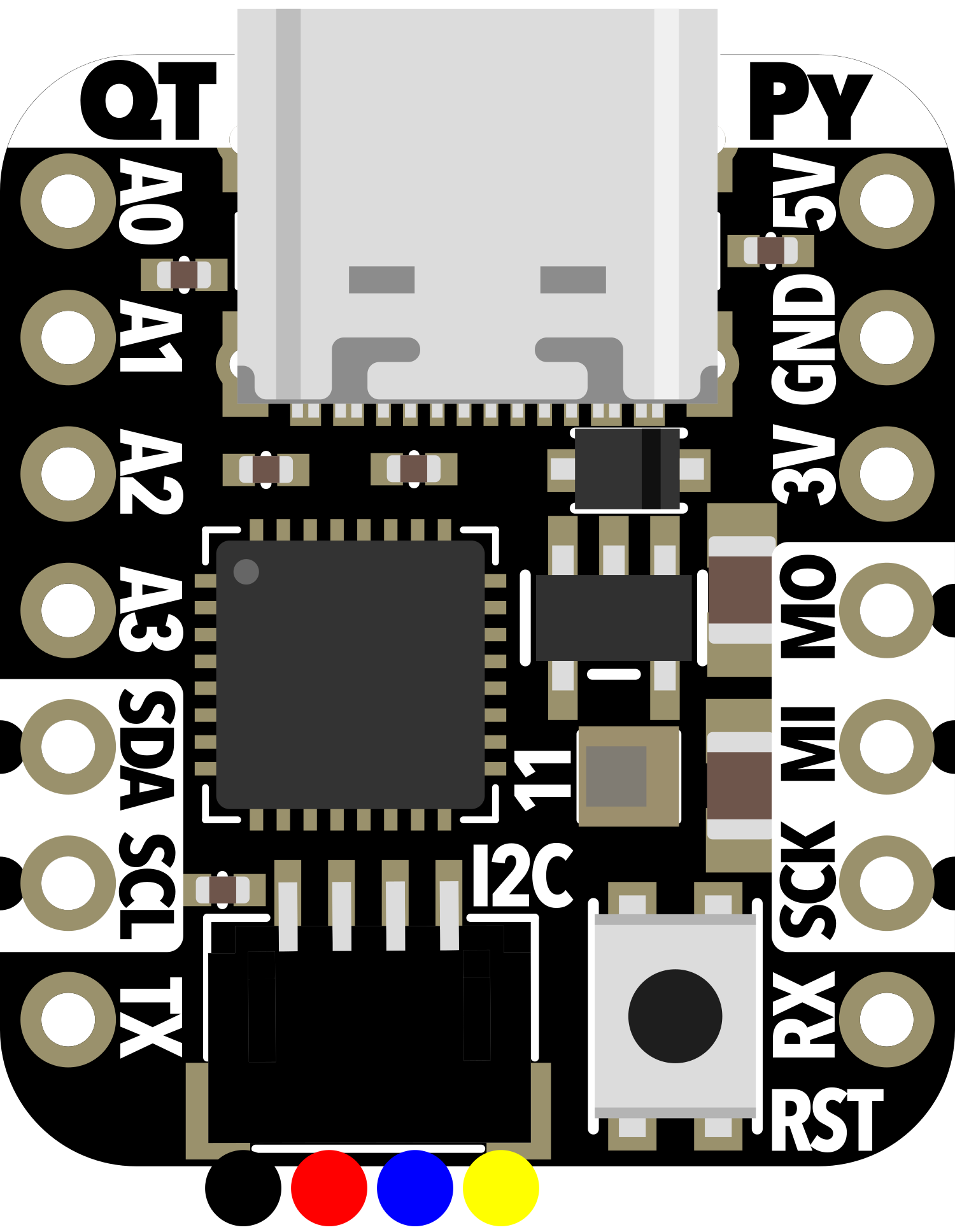
Pin Configuration and Descriptions
| Pin # | Function | Description |
|---|---|---|
| 1 | A0/D0 | Analog input or digital I/O, PWM |
| 2 | A1/D1 | Analog input or digital I/O, PWM, DAC |
| 3 | A2/D2 | Analog input or digital I/O, PWM |
| 4 | A3/D3 | Analog input or digital I/O, PWM |
| 5 | SDA | I2C data line |
| 6 | SCL | I2C clock line |
| 7 | TX | UART transmit |
| 8 | RX | UART receive |
| 9 | SCK | SPI clock |
| 10 | MO | SPI master out, slave in |
| 11 | MI | SPI master in, slave out |
| - | GND | Ground |
| - | 3V | 3.3V power supply |
| - | RST | Reset pin |
| - | USB | USB-C for programming and power |
Usage Instructions
How to Use the Component in a Circuit
- Powering the Board: Connect the USB-C cable to the QT Py and a power source or computer to power the board.
- Programming: Use the Arduino IDE or CircuitPython to write and upload code to the QT Py.
- Connecting Peripherals: Use the GPIO pins to connect sensors, actuators, or other peripherals. Ensure that the connected devices are compatible with the board's operating voltage (3.3V).
Important Considerations and Best Practices
- Voltage Levels: The QT Py operates at 3.3V. Connecting peripherals that require 5V or higher can damage the board.
- Current Draw: Be mindful of the current draw from the GPIO pins. Excessive current can damage the board or the connected peripherals.
- ESD Precautions: As with all microcontroller boards, take precautions against electrostatic discharge (ESD) when handling.
- Firmware Updates: Keep the board's firmware updated for the best performance and compatibility with the latest features.
Troubleshooting and FAQs
Common Issues Users Might Face
- Board Not Recognized: Ensure the USB-C cable is properly connected and the computer's USB port is functioning. Try a different cable or port if necessary.
- Code Not Running: Verify that the code is correctly written and uploaded to the board. Check for syntax errors or incorrect pin assignments.
- Peripheral Issues: If a connected peripheral is not working, check the wiring and ensure that it is compatible with the board's voltage levels.
Solutions and Tips for Troubleshooting
- LED Not Lighting Up: Check the code for proper NeoPixel library usage and ensure that the correct pin is being addressed.
- Board Not Powering On: Check the USB-C connection and ensure that the power source is supplying the correct voltage.
- Connectivity Issues: If using I2C or SPI, ensure that the connections are correct and that pull-up resistors are in place if required.
FAQs
Q: Can I power the QT Py with a battery? A: Yes, you can power the QT Py with a battery, but ensure that the voltage is within the recommended input voltage range.
Q: Is the QT Py breadboard-friendly? A: Yes, the QT Py is designed with breadboard-friendly spacing.
Q: How do I reset the board? A: Briefly press the RST button to reset the board. Double-press to enter the bootloader mode for firmware updates.
Example Code for Arduino UNO
Below is a simple example code that blinks the onboard NeoPixel LED on the Adafruit QT Py using the Arduino IDE.
#include <Adafruit_NeoPixel.h>

#define PIN        0  // Define the pin for the NeoPixel
#define NUMPIXELS  1  // Number of pixels in the NeoPixel

// Initialize the NeoPixel library.
Adafruit_NeoPixel pixels(NUMPIXELS, PIN, NEO_GRB + NEO_KHZ800);

void setup() {
  pixels.begin(); // Initialize the NeoPixel
}

void loop() {
  pixels.setPixelColor(0, pixels.Color(150, 0, 0)); // Set the color to red
  pixels.show();   // Send the updated pixel colors to the hardware.
  delay(500);      // Wait for half a second
  pixels.clear();  // Turn off the NeoPixel
  pixels.show();
  delay(500);      // Wait for half a second
}
Remember to install the Adafruit_NeoPixel library through the Arduino Library Manager before uploading this code to the QT Py. This example assumes that the onboard NeoPixel is connected to pin 0, which is the default for the Adafruit QT Py.