How to Use MAX9814: Examples, Pinouts, and Specs
Introduction
The MAX9814 is a low-noise microphone preamplifier with an integrated automatic gain control (AGC) circuit, designed to deliver high-quality audio performance. Manufactured by Arduino, this component is ideal for applications requiring consistent audio levels and minimal distortion. The built-in AGC dynamically adjusts the gain based on the input signal level, ensuring clear and consistent audio output.
Explore Projects Built with MAX9814


Explore Projects Built with MAX9814
Common Applications
- Voice recognition systems
- Portable audio devices
- Conference systems
- Smart home devices (e.g., voice assistants)
- Audio recording equipment
Technical Specifications
Key Technical Details
- Supply Voltage (Vcc): 2.7V to 5.5V
- Quiescent Current: 3mA (typical)
- Input Signal Range: 20mV to 1V (RMS)
- Output Voltage Swing: 200mV to Vcc - 200mV
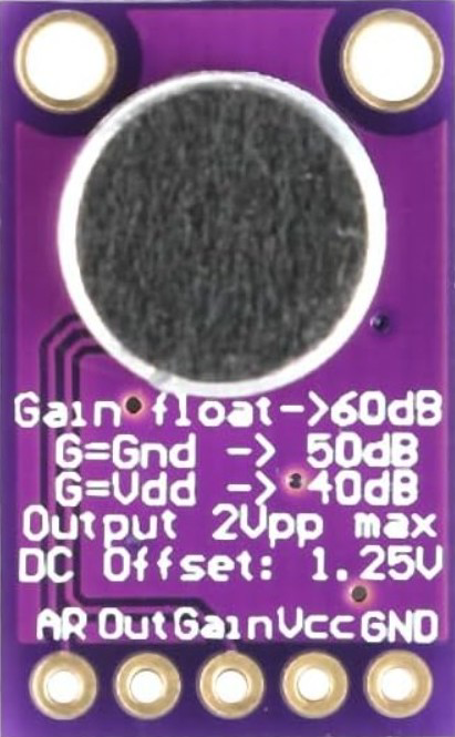
- Automatic Gain Control (AGC): Adjustable from 40dB to 60dB
- Noise Performance: Low-noise design for high-quality audio
- Operating Temperature Range: -40°C to +85°C
- Package Type: 8-pin SOIC or TDFN
Pin Configuration and Descriptions
The MAX9814 has 8 pins, each serving a specific function. The table below outlines the pin configuration:
| Pin Number | Pin Name | Description |
|---|---|---|
| 1 | OUT | Audio output signal. Connect to the next stage of the audio circuit. |
| 2 | GND | Ground. Connect to the system ground. |
| 3 | Vcc | Power supply input. Connect to a 2.7V to 5.5V power source. |
| 4 | BYPASS | Bypass capacitor connection for noise filtering. Connect a 0.1µF capacitor. |
| 5 | IN+ | Non-inverting microphone input. Connect to the positive terminal of the mic. |
| 6 | IN- | Inverting microphone input. Connect to the negative terminal of the mic. |
| 7 | GAIN | Gain control pin. Connect a resistor to set the gain level. |
| 8 | TH | Threshold pin for AGC. Connect a resistor to set the AGC threshold. |
Usage Instructions
How to Use the MAX9814 in a Circuit
- Power Supply: Connect the Vcc pin to a stable power source (2.7V to 5.5V) and the GND pin to the system ground.
- Microphone Connection: Connect the microphone's positive terminal to the IN+ pin and the negative terminal to the IN- pin.
- Bypass Capacitor: Place a 0.1µF capacitor between the BYPASS pin and ground to filter noise.
- Gain Adjustment: Connect a resistor to the GAIN pin to set the desired gain level. Refer to the datasheet for resistor values corresponding to specific gain levels.
- AGC Threshold: Connect a resistor to the TH pin to set the AGC threshold. This determines the input signal level at which the AGC activates.
- Output Connection: Connect the OUT pin to the next stage of the audio circuit, such as an amplifier or ADC.
Important Considerations and Best Practices
- Use decoupling capacitors (e.g., 0.1µF) near the Vcc pin to stabilize the power supply and reduce noise.
- Ensure proper grounding to minimize interference and noise in the audio signal.
- Select appropriate resistor values for the GAIN and TH pins based on your application requirements.
- Avoid placing the MAX9814 near high-frequency components to prevent interference.
Example: Connecting the MAX9814 to an Arduino UNO
The MAX9814 can be easily interfaced with an Arduino UNO for audio signal processing. Below is an example circuit and code:
Circuit Connections
- Vcc: Connect to the Arduino's 5V pin.
- GND: Connect to the Arduino's GND pin.
- OUT: Connect to an analog input pin on the Arduino (e.g., A0).
- IN+ and IN-: Connect to the microphone terminals.
- GAIN and TH: Connect appropriate resistors to set gain and AGC threshold.
Arduino Code Example
// MAX9814 Audio Signal Processing Example
// Reads audio signal from the MAX9814 and prints the analog value to the Serial Monitor

const int audioPin = A0; // Analog pin connected to MAX9814 OUT pin

void setup() {
  Serial.begin(9600); // Initialize serial communication at 9600 baud
}

void loop() {
  int audioValue = analogRead(audioPin); // Read the audio signal
  Serial.println(audioValue); // Print the audio signal value to the Serial Monitor
  delay(10); // Small delay to avoid overwhelming the Serial Monitor
}
Troubleshooting and FAQs
Common Issues and Solutions
No Output Signal:
- Cause: Incorrect wiring or loose connections.
- Solution: Double-check all connections, especially the microphone and power supply.
Distorted Audio Output:
- Cause: Incorrect gain or AGC threshold settings.
- Solution: Adjust the resistor values on the GAIN and TH pins to optimize performance.
High Noise Levels:
- Cause: Poor grounding or insufficient bypass capacitor.
- Solution: Ensure proper grounding and use a 0.1µF capacitor on the BYPASS pin.
Low Output Volume:
- Cause: Low input signal or incorrect gain settings.
- Solution: Increase the microphone input level or adjust the gain resistor.
FAQs
Q1: Can the MAX9814 work with a 3.3V power supply?
Yes, the MAX9814 operates within a supply voltage range of 2.7V to 5.5V, making it compatible with 3.3V systems.
Q2: What type of microphone is compatible with the MAX9814?
The MAX9814 is designed for use with electret microphones.
Q3: How do I calculate the resistor values for the GAIN and TH pins?
Refer to the MAX9814 datasheet for detailed resistor value tables corresponding to specific gain and AGC threshold levels.
Q4: Can I use the MAX9814 for stereo audio applications?
No, the MAX9814 is a single-channel preamplifier. For stereo applications, you will need two MAX9814 modules.
Q5: Is the MAX9814 suitable for battery-powered devices?
Yes, the MAX9814's low quiescent current (3mA typical) makes it ideal for battery-powered applications.