
How to Use 50-PIN-CENTRONICS-M: Examples, Pinouts, and Specs
 Design with 50-PIN-CENTRONICS-M in Cirkit Designer
Introduction
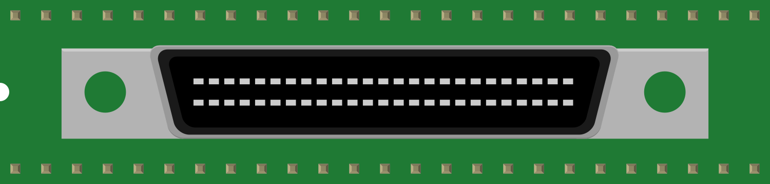
The 50-PIN-CENTRONICS-M is a male connector designed for parallel communication. It is widely used in legacy systems, particularly in printers, scanners, and other peripheral devices, to facilitate high-speed data transfer between devices. This connector adheres to the Centronics standard, which was a popular interface for parallel data communication in the late 20th century.
Explore Projects Built with 50-PIN-CENTRONICS-M
 Open Project in Cirkit Designer
 Open Project in Cirkit Designer
 Open Project in Cirkit Designer
 Open Project in Cirkit Designer
Explore Projects Built with 50-PIN-CENTRONICS-M
Open Project in Cirkit DesignerOpen Project in Cirkit DesignerOpen Project in Cirkit DesignerOpen Project in Cirkit DesignerCommon Applications and Use Cases
- Printers and Scanners: Used to connect printers and scanners to computers or other devices.
- Industrial Equipment: Found in older industrial systems requiring parallel data transfer.
- Legacy Systems: Ideal for maintaining or repairing older systems that rely on Centronics interfaces.
- Data Acquisition Systems: Used in setups where multiple data lines need to be transmitted simultaneously.
Technical Specifications
Key Technical Details
- Connector Type: 50-pin Centronics male
- Interface Standard: Parallel communication
- Number of Pins: 50
- Pin Pitch: 2.16 mm (0.085 inches)
- Voltage Rating: Typically supports 5V logic levels
- Current Rating: Up to 1A per pin
- Operating Temperature: -20°C to 70°C
- Material:
- Contacts: Gold-plated for improved conductivity and corrosion resistance
- Housing: Durable plastic or metal shell for mechanical stability
Pin Configuration and Descriptions
The 50-PIN-CENTRONICS-M connector has 50 pins arranged in two rows. Below is the pinout and description for each pin:
| Pin Number | Signal Name | Description |
|---|---|---|
| 1-8 | Data 1 to Data 8 | Parallel data lines for transmitting 8-bit data. |
| 9 | Strobe | Signal to indicate the start of data transfer. |
| 10 | Acknowledge | Signal from the peripheral to acknowledge data receipt. |
| 11 | Busy | Indicates the peripheral is busy and cannot accept data. |
| 12 | Paper End | Indicates the printer is out of paper. |
| 13 | Select | Indicates the peripheral is selected. |
| 14 | Auto Feed | Controls automatic paper feeding. |
| 15 | Error | Indicates an error condition in the peripheral. |
| 16-17 | Ground | Common ground for the signals. |
| 18-25 | Data 9 to Data 16 | Additional parallel data lines for extended communication. |
| 26-50 | Reserved/Custom Use | Reserved for custom or manufacturer-specific signals. |
Note: Pin assignments may vary slightly depending on the specific device or manufacturer. Always refer to the device's datasheet for exact pin configurations.
Usage Instructions
How to Use the Component in a Circuit
- Connection: Align the 50-PIN-CENTRONICS-M connector with the corresponding female port on the peripheral device. Ensure a secure fit to avoid loose connections.
- Wiring: Use a parallel cable with matching pinouts to connect the male connector to the host device (e.g., computer or controller).
- Signal Levels: Ensure the voltage levels of the connected devices are compatible (typically 5V logic).
- Termination: If the cable length is significant, consider adding termination resistors to reduce signal reflections and maintain data integrity.
Important Considerations and Best Practices
- Cable Length: Keep the cable length as short as possible to minimize signal degradation and interference.
- Shielding: Use shielded cables to reduce electromagnetic interference (EMI) in noisy environments.
- Compatibility: Verify that the connected devices support the Centronics standard and pinout.
- Maintenance: Periodically clean the connector pins to ensure reliable electrical contact.
Example: Connecting to an Arduino UNO
While the 50-PIN-CENTRONICS-M is not directly compatible with modern microcontrollers like the Arduino UNO, it can be interfaced using additional circuitry such as shift registers or parallel-to-serial converters. Below is an example of interfacing the connector to an Arduino for basic data transmission:
// Example: Sending 8-bit data to a Centronics-compatible device
// This example assumes the use of digital pins 2-9 for data lines (D0-D7)
// and pin 10 for the strobe signal.

#define STROBE_PIN 10  // Define the strobe signal pin
#define DATA_PINS_START 2  // Starting pin for data lines (D0)

// Function to send 8-bit data
void sendData(uint8_t data) {
  for (int i = 0; i < 8; i++) {
    // Write each bit of the data to the corresponding pin
    digitalWrite(DATA_PINS_START + i, (data >> i) & 0x01);
  }
  // Pulse the strobe signal to indicate data is ready
  digitalWrite(STROBE_PIN, HIGH);
  delayMicroseconds(10);  // Short delay for strobe pulse
  digitalWrite(STROBE_PIN, LOW);
}

void setup() {
  // Set data pins and strobe pin as outputs
  for (int i = 0; i < 8; i++) {
    pinMode(DATA_PINS_START + i, OUTPUT);
  }
  pinMode(STROBE_PIN, OUTPUT);
  digitalWrite(STROBE_PIN, LOW);  // Initialize strobe pin to LOW
}

void loop() {
  // Example: Send the ASCII character 'A' (binary 01000001)
  sendData(0x41);
  delay(1000);  // Wait 1 second before sending the next character
}
Note: Ensure proper level shifting if the peripheral device operates at voltage levels different from the Arduino's 5V logic.
Troubleshooting and FAQs
Common Issues Users Might Face
- Loose Connection: The connector may not be securely attached, leading to intermittent communication.
- Solution: Ensure the connector is firmly seated and the locking clips (if present) are engaged.
- Signal Noise: Long cables or unshielded connections can introduce noise, causing data corruption.
- Solution: Use shorter, shielded cables and add termination resistors if necessary.
- Incorrect Pinout: Miswiring the connector can result in malfunction or damage to the devices.
- Solution: Double-check the pinout and wiring before powering the system.
- Device Not Responding: The peripheral device may not acknowledge data or respond to commands.
- Solution: Verify the device's power supply, compatibility, and configuration settings.
FAQs
Q: Can I use the 50-PIN-CENTRONICS-M with modern USB interfaces?
A: Yes, but you will need a Centronics-to-USB adapter to bridge the communication gap.Q: What is the maximum data transfer rate for this connector?
A: The Centronics standard typically supports data rates up to 1 MB/s, depending on the cable length and signal quality.Q: Is this connector still widely used?
A: While it is less common in modern systems, it is still used in legacy and industrial applications.Q: Can I use this connector for serial communication?
A: No, the 50-PIN-CENTRONICS-M is designed for parallel communication, not serial.
By following this documentation, users can effectively utilize the 50-PIN-CENTRONICS-M connector in their projects and troubleshoot common issues.