How to Use dc-dc buck converter 25w module: Examples, Pinouts, and Specs
Introduction
The DC-DC Buck Converter 25W Module (Manufacturer Part ID: DFR0205) by DFRobot is a high-efficiency voltage step-down module designed to convert a higher DC input voltage to a lower DC output voltage. This module is capable of delivering up to 25 watts of power, making it ideal for applications requiring efficient power regulation.
Explore Projects Built with dc-dc buck converter 25w module


Explore Projects Built with dc-dc buck converter 25w module
Common Applications and Use Cases
- Powering low-voltage devices from higher-voltage sources (e.g., 12V to 5V conversion)
- Battery-powered systems to regulate voltage levels
- Robotics and IoT projects
- LED lighting systems
- Arduino and microcontroller-based projects
Technical Specifications
The following table outlines the key technical details of the DFR0205 module:
| Parameter | Value |
|---|---|
| Input Voltage Range | 6V to 32V DC |
| Output Voltage Range | 1.25V to 32V DC (adjustable) |
| Maximum Output Power | 25W |
| Maximum Output Current | 5A (with proper heat dissipation) |
| Efficiency | Up to 96% |
| Switching Frequency | 150 kHz |
| Operating Temperature | -40°C to +85°C |
| Dimensions | 43mm x 21mm x 14mm |
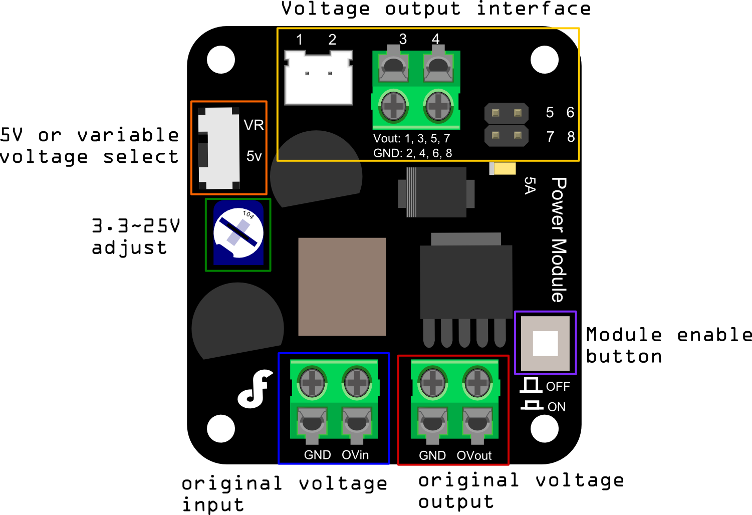
Pin Configuration and Descriptions
The DFR0205 module has the following pin layout:
| Pin Name | Description |
|---|---|
| VIN+ | Positive input voltage terminal (connect to the higher DC voltage source) |
| VIN- | Negative input voltage terminal (connect to the ground of the DC voltage source) |
| VOUT+ | Positive output voltage terminal (connect to the load's positive terminal) |
| VOUT- | Negative output voltage terminal (connect to the load's ground terminal) |
Usage Instructions
How to Use the Component in a Circuit
Connect the Input Voltage:
- Connect the VIN+ pin to the positive terminal of your DC power source.
- Connect the VIN- pin to the ground terminal of your DC power source.
- Ensure the input voltage is within the range of 6V to 32V DC.
Connect the Output Voltage:
- Connect the VOUT+ pin to the positive terminal of your load.
- Connect the VOUT- pin to the ground terminal of your load.
Adjust the Output Voltage:
- Use the onboard potentiometer to adjust the output voltage.
- Turn the potentiometer clockwise to increase the output voltage and counterclockwise to decrease it.
- Use a multimeter to measure the output voltage while adjusting to ensure accuracy.
Heat Dissipation:
- For currents above 3A, ensure proper heat dissipation by attaching a heatsink or using active cooling (e.g., a fan).
Important Considerations and Best Practices
- Input Voltage: Ensure the input voltage is always higher than the desired output voltage.
- Current Limitation: Do not exceed the maximum output current of 5A. Use proper cooling for high-current applications.
- Polarity: Double-check the polarity of the input and output connections to avoid damage to the module.
- Load Testing: Test the module with a dummy load before connecting sensitive devices.
Example: Using the DFR0205 with an Arduino UNO
The DFR0205 can be used to power an Arduino UNO by stepping down a 12V DC input to 5V DC. Below is an example circuit and Arduino code to blink an LED:
Circuit Connections
- Connect a 12V DC power source to the VIN+ and VIN- pins of the DFR0205.
- Adjust the output voltage to 5V DC using the potentiometer.
- Connect the VOUT+ pin to the Arduino UNO's 5V pin.
- Connect the VOUT- pin to the Arduino UNO's GND pin.
- Connect an LED to pin 13 of the Arduino UNO with a 220-ohm resistor in series.
Arduino Code
// Blink an LED connected to pin 13 of the Arduino UNO
// Ensure the DFR0205 module is providing a stable 5V to the Arduino

void setup() {
  pinMode(13, OUTPUT); // Set pin 13 as an output
}

void loop() {
  digitalWrite(13, HIGH); // Turn the LED on
  delay(1000);            // Wait for 1 second
  digitalWrite(13, LOW);  // Turn the LED off
  delay(1000);            // Wait for 1 second
}
Troubleshooting and FAQs
Common Issues and Solutions
No Output Voltage:
- Cause: Incorrect input connections or insufficient input voltage.
- Solution: Verify the polarity and ensure the input voltage is within the specified range.
Output Voltage Fluctuations:
- Cause: Load exceeds the module's current capacity or poor heat dissipation.
- Solution: Reduce the load or improve heat dissipation with a heatsink or fan.
Module Overheating:
- Cause: High current draw without proper cooling.
- Solution: Attach a heatsink or use active cooling for currents above 3A.
Cannot Adjust Output Voltage:
- Cause: Faulty potentiometer or incorrect input voltage.
- Solution: Check the input voltage and ensure it is higher than the desired output voltage. If the issue persists, inspect the potentiometer.
FAQs
Q1: Can the DFR0205 be used with a battery as the input source?
A1: Yes, the module can be powered by a DC battery as long as the voltage is within the range of 6V to 32V.
Q2: What is the maximum efficiency of the module?
A2: The module can achieve an efficiency of up to 96%, depending on the input and output voltage difference and the load.
Q3: Can I use this module to power a Raspberry Pi?
A3: Yes, you can use the DFR0205 to step down a higher voltage (e.g., 12V) to 5V to power a Raspberry Pi. Ensure the output voltage is precisely set to 5V before connecting the Raspberry Pi.
Q4: Is the module protected against reverse polarity?
A4: No, the module does not have built-in reverse polarity protection. Always double-check your connections to avoid damage.
Q5: Can I use this module for AC voltage conversion?
A5: No, the DFR0205 is designed for DC-to-DC conversion only. Do not connect it to an AC power source.