How to Use Adafruit QT Py RP2040: Examples, Pinouts, and Specs
Introduction
The Adafruit QT Py RP2040 is a compact and versatile microcontroller board that harnesses the capabilities of the Raspberry Pi RP2040 microcontroller. With its ARM Cortex-M0+ processor clocked at 133MHz, it is well-suited for a variety of projects ranging from simple LED blinkers to more complex IoT devices. The board's small form factor, combined with its ample 8MB of flash memory and an additional 4MB of SPI flash, makes it ideal for wearable tech, portable projects, and space-constrained applications. The QT Py RP2040 also features a range of connectivity options, including I2C, SPI, UART, and analog inputs, along with 11 GPIO pins, providing ample flexibility for interfacing with various sensors and peripherals.
Explore Projects Built with Adafruit QT Py RP2040


Explore Projects Built with Adafruit QT Py RP2040
Technical Specifications
Key Technical Details
- Microcontroller: Raspberry Pi RP2040
- Processor: ARM Cortex-M0+ running at 133MHz
- Flash Memory: 8MB (onboard)
- Extra SPI Flash: 4MB
- USB Support: Built-in, with USB-C connector
- GPIO Pins: 11, with multiple functions
- Interfaces: I2C, SPI, UART
- Analog Inputs: Available on certain GPIO pins
- Power Supply: 5V via USB-C or battery input
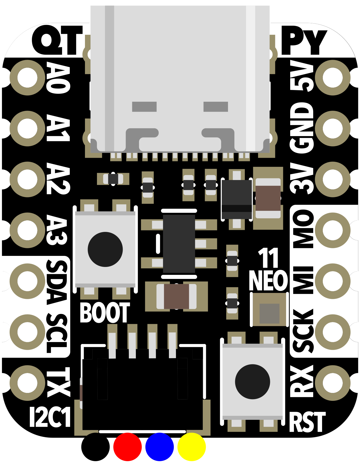
Pin Configuration and Descriptions
| Pin Number | Function | Description |
|---|---|---|
| 1 | GP0/A0 | General-purpose I/O, Analog Input 0 |
| 2 | GP1/A1 | General-purpose I/O, Analog Input 1 |
| 3 | GP2/A2 | General-purpose I/O, Analog Input 2 |
| 4 | GP3/A3 | General-purpose I/O, Analog Input 3 |
| 5 | GP4 | General-purpose I/O |
| 6 | GP5 | General-purpose I/O |
| 7 | GP6/SCK | General-purpose I/O, SPI Clock |
| 8 | GP7/MOSI | General-purpose I/O, SPI Master Out Slave In |
| 9 | GP8/MISO | General-purpose I/O, SPI Master In Slave Out |
| 10 | GP9/UART TX | General-purpose I/O, UART Transmit |
| 11 | GP10/UART RX | General-purpose I/O, UART Receive |
Usage Instructions
Integrating with a Circuit
To use the Adafruit QT Py RP2040 in a circuit:
- Connect the board to your computer using a USB-C cable to provide power and enable programming.
- Ensure that the necessary drivers and board definitions are installed in your development environment (e.g., Arduino IDE or CircuitPython).
- Connect sensors, actuators, or other peripherals to the GPIO pins, taking care to match the voltage levels and respect the maximum current ratings.
Best Practices
- Use a current-limiting resistor when connecting LEDs to GPIO pins.
- When using analog inputs, ensure that the input voltage does not exceed the maximum allowed voltage for the board.
- Avoid drawing too much current from the GPIO pins to prevent damage to the board.
- Implement proper debouncing when using switches or buttons.
Example Code for Arduino UNO
Here is a simple example of how to blink an LED connected to pin GP0 on the Adafruit QT Py RP2040 using Arduino code:
// Define the LED pin
const int ledPin = 0; // GP0/A0 as LED pin

// Setup function runs once at the start
void setup() {
  // Initialize the LED pin as an output
  pinMode(ledPin, OUTPUT);
}

// Loop function runs repeatedly
void loop() {
  digitalWrite(ledPin, HIGH); // Turn the LED on
  delay(1000);                // Wait for a second
  digitalWrite(ledPin, LOW);  // Turn the LED off
  delay(1000);                // Wait for a second
}
Ensure that you select the correct board and port in your Arduino IDE before uploading the code to the Adafruit QT Py RP2040.
Troubleshooting and FAQs
Common Issues
- Board not recognized by computer: Ensure that the USB-C cable is properly connected and that the cable supports data transfer.
- Cannot upload code: Check that the correct board and port are selected in the development environment. Also, ensure that the bootloader is functioning correctly.
- Unexpected behavior in circuits: Verify that all connections are secure and that components are functioning as expected. Check for shorts or incorrect wiring.
Solutions and Tips
- If the board is not recognized, try using a different USB-C cable or port.
- For upload issues, double-check the board settings and drivers. If necessary, reset the board into bootloader mode.
- Use a multimeter to check for continuity and correct voltages in your circuit.
FAQs
Q: What is the maximum voltage for the analog inputs? A: The maximum voltage for the analog inputs is typically 3.3V.
Q: Can I power the board with a battery? A: Yes, the board can be powered with a battery. Ensure that the battery voltage is compatible with the board's requirements.
Q: How do I use the extra SPI flash? A: The extra SPI flash can be used for storing data or code. Accessing it requires specific libraries and code, which can be found in the Adafruit documentation for the board.
For further assistance, consult the Adafruit forums or the detailed documentation available on the Adafruit website.