
How to Use SSR DC - DC: Examples, Pinouts, and Specs
 Design with SSR DC - DC in Cirkit Designer
Introduction
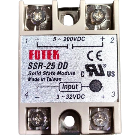
The Fotek SSR DC-DC is a Solid State Relay (SSR) designed specifically for DC applications. It enables the control of high-voltage DC loads using low-voltage control signals. Unlike traditional mechanical relays, the SSR DC-DC offers fast switching, high reliability, and no mechanical wear, making it ideal for applications requiring frequent switching or high durability.
Explore Projects Built with SSR DC - DC
 Open Project in Cirkit Designer
 Open Project in Cirkit Designer
 Open Project in Cirkit Designer
 Open Project in Cirkit Designer
Explore Projects Built with SSR DC - DC
Open Project in Cirkit DesignerOpen Project in Cirkit DesignerOpen Project in Cirkit DesignerOpen Project in Cirkit DesignerCommon Applications and Use Cases
- Industrial automation systems
- Motor control in DC circuits
- Battery management systems
- Solar power systems
- LED lighting control
- Robotics and mechatronics
Technical Specifications
The Fotek SSR DC-DC is engineered to handle a wide range of DC control and load requirements. Below are the key technical details:
General Specifications
| Parameter | Value |
|---|---|
| Manufacturer | Fotek |
| Part ID | Not specified |
| Type | Solid State Relay (SSR) |
| Control Signal Voltage | 3-32 VDC |
| Load Voltage Range | 5-220 VDC |
| Maximum Load Current | 40 A |
| Isolation Voltage | ≥ 2500 V |
| Switching Speed | ≤ 10 ms |
| Operating Temperature | -30°C to +80°C |
| Storage Temperature | -30°C to +100°C |
| Mounting Type | Panel Mount |
Pin Configuration and Descriptions
The SSR DC-DC typically has four terminals, as described below:
| Pin Number | Label | Description |
|---|---|---|
| 1 | Input (+) | Positive terminal for the control signal |
| 2 | Input (-) | Negative terminal for the control signal |
| 3 | Load (+) | Positive terminal for the DC load |
| 4 | Load (-) | Negative terminal for the DC load |
Usage Instructions
How to Use the SSR DC-DC in a Circuit
Control Signal Connection:
- Connect the positive control signal to the
Input (+)terminal (Pin 1). - Connect the negative control signal to the
Input (-)terminal (Pin 2). - Ensure the control signal voltage is within the specified range (3-32 VDC).
- Connect the positive control signal to the
Load Connection:
- Connect the positive side of the DC load to the
Load (+)terminal (Pin 3). - Connect the negative side of the DC load to the
Load (-)terminal (Pin 4). - Ensure the load voltage and current do not exceed the relay's maximum ratings.
- Connect the positive side of the DC load to the
Power Supply:
- Verify that the power supply for the control signal and the load are properly isolated if required.
- Double-check all connections before powering the circuit.
Mounting:
- Securely mount the SSR on a heat sink or panel to ensure proper heat dissipation.
- Use thermal paste if necessary to improve heat transfer.
Important Considerations and Best Practices
- Heat Dissipation: The SSR may generate heat during operation. Use a heat sink or cooling fan to prevent overheating.
- Voltage Spikes: For inductive loads, use a flyback diode across the load terminals to suppress voltage spikes.
- Polarity: Ensure correct polarity for both the control signal and load connections to avoid damage.
- Isolation: Maintain proper isolation between the control and load circuits to prevent electrical interference.
- Testing: Test the SSR in a low-power setup before integrating it into a high-power application.
Example: Using the SSR DC-DC with an Arduino UNO
Below is an example of how to control the SSR DC-DC using an Arduino UNO:
// Example: Controlling a Fotek SSR DC-DC with Arduino UNO
// This code toggles the SSR on and off every 2 seconds.

const int ssrPin = 9; // Pin connected to the SSR control input

void setup() {
  pinMode(ssrPin, OUTPUT); // Set the SSR pin as an output
}

void loop() {
  digitalWrite(ssrPin, HIGH); // Turn the SSR on
  delay(2000);                // Wait for 2 seconds
  digitalWrite(ssrPin, LOW);  // Turn the SSR off
  delay(2000);                // Wait for 2 seconds
}
Note: Use a current-limiting resistor if required to protect the Arduino pin.
Troubleshooting and FAQs
Common Issues and Solutions
SSR Not Switching:
- Cause: Insufficient control signal voltage.
- Solution: Verify that the control signal voltage is within the 3-32 VDC range.
Overheating:
- Cause: Excessive load current or inadequate heat dissipation.
- Solution: Ensure the load current does not exceed 40 A. Use a heat sink or cooling fan.
Load Not Turning Off:
- Cause: Inductive load causing voltage spikes.
- Solution: Add a flyback diode across the load terminals.
Control Signal Interference:
- Cause: Electrical noise in the control circuit.
- Solution: Use shielded cables or add a capacitor across the control input terminals.
FAQs
Q1: Can the SSR DC-DC be used with AC loads?
A1: No, this SSR is designed specifically for DC loads. For AC loads, use an AC-AC or DC-AC SSR.
Q2: What happens if the load current exceeds 40 A?
A2: Exceeding the maximum load current can damage the SSR. Always ensure the load current is within the specified limit.
Q3: Is the SSR polarity-sensitive?
A3: Yes, both the control signal and load connections are polarity-sensitive. Incorrect polarity can damage the relay.
Q4: Can I use the SSR without a heat sink?
A4: It is not recommended. Without proper heat dissipation, the SSR may overheat and fail.
By following this documentation, users can effectively integrate the Fotek SSR DC-DC into their projects and ensure reliable operation.