
How to Use ArduPilot Mega v1.5: Examples, Pinouts, and Specs
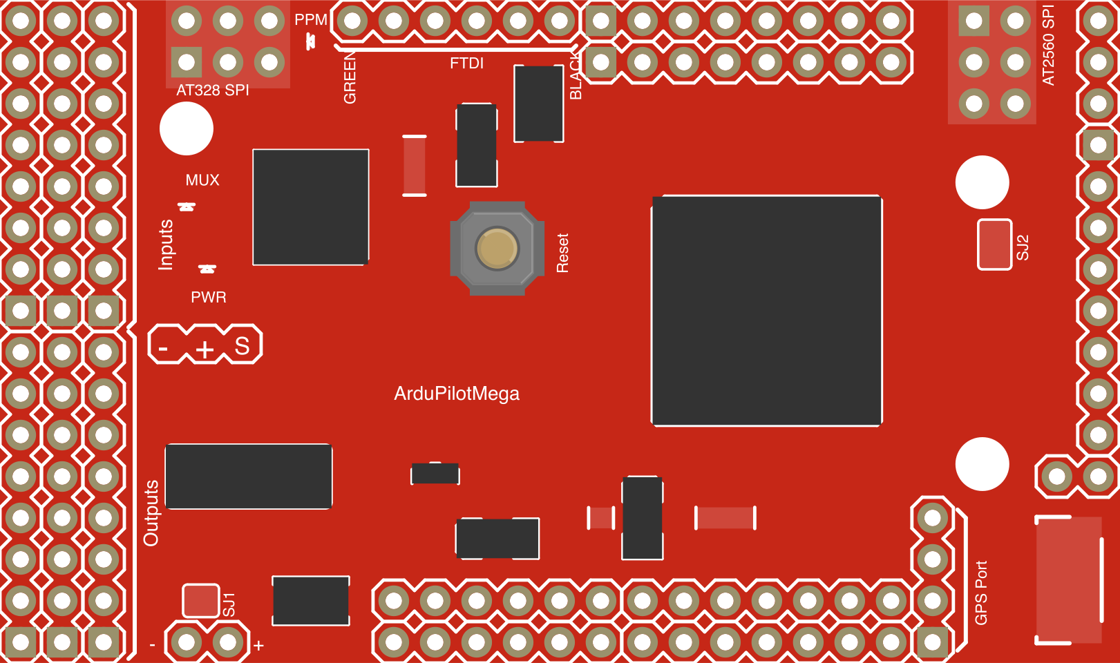
 Design with ArduPilot Mega v1.5 in Cirkit Designer
Introduction
The ArduPilot Mega v1.5, manufactured by SparkFun Electronics, is a versatile open-source autopilot platform designed for controlling various types of unmanned vehicles, such as drones, rovers, and boats. It features advanced flight control algorithms and supports a wide range of sensors, making it an ideal choice for hobbyists, researchers, and developers working on autonomous systems.
Explore Projects Built with ArduPilot Mega v1.5
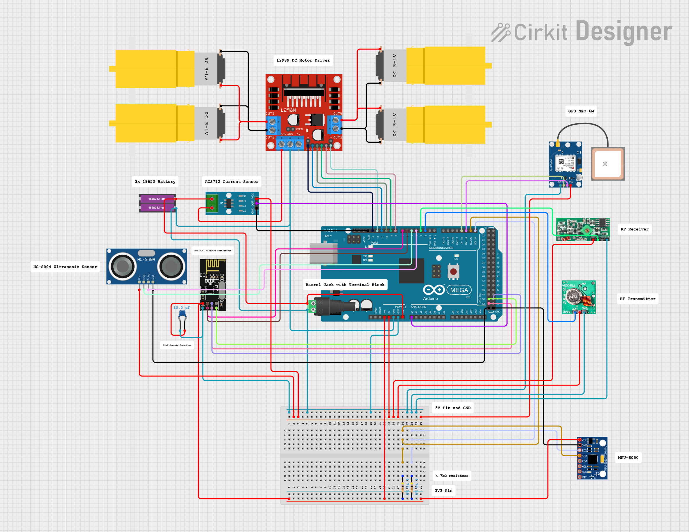 Open Project in Cirkit Designer
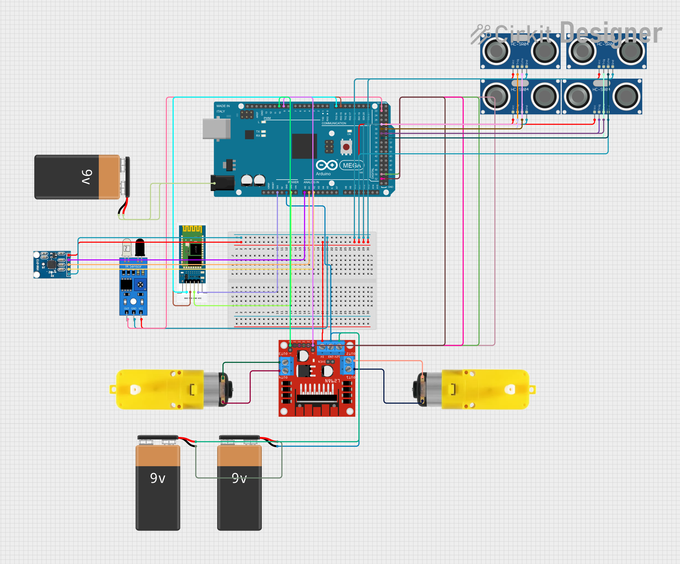 Open Project in Cirkit Designer
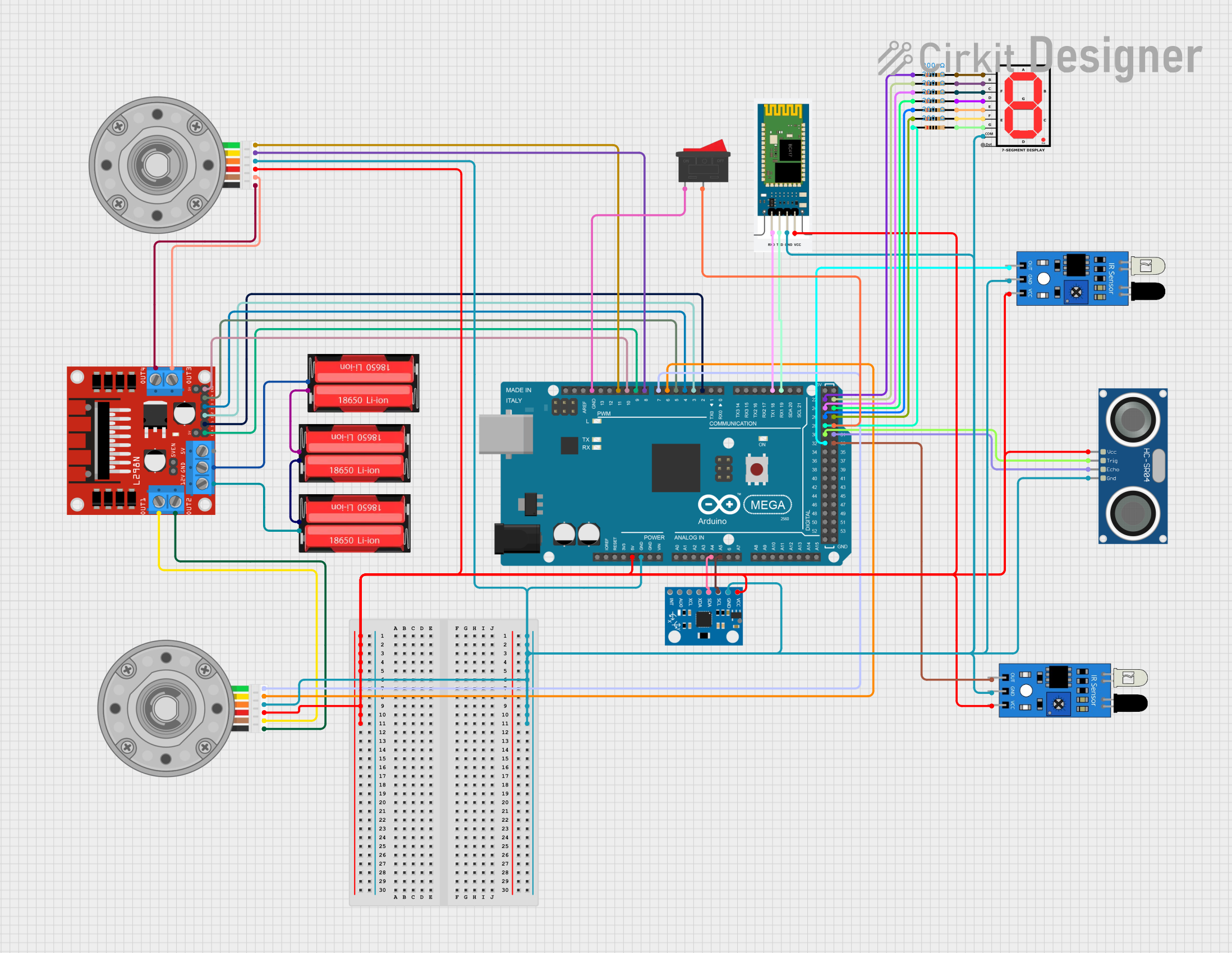 Open Project in Cirkit Designer
 Open Project in Cirkit Designer
Explore Projects Built with ArduPilot Mega v1.5
Open Project in Cirkit DesignerOpen Project in Cirkit DesignerOpen Project in Cirkit DesignerOpen Project in Cirkit DesignerCommon Applications and Use Cases
- Autonomous drones (quadcopters, hexacopters, etc.)
- Ground-based rovers and vehicles
- Autonomous boats and submarines
- Research and development in robotics and control systems
- Educational projects in embedded systems and flight control
Technical Specifications
Key Technical Details
- Microcontroller: ATmega1280 (8-bit AVR, 16 MHz)
- Input Voltage: 5V (regulated) or 6-16V (unregulated)
- Power Consumption: ~500 mA (depending on connected peripherals)
- I/O Pins: 52 digital I/O pins (14 PWM outputs)
- Analog Inputs: 16 channels (10-bit resolution)
- Communication Interfaces: UART, I2C, SPI
- Flash Memory: 128 KB (4 KB used by bootloader)
- SRAM: 8 KB
- EEPROM: 4 KB
- Dimensions: 61 mm x 61 mm
- Weight: ~20 g
Pin Configuration and Descriptions
The ArduPilot Mega v1.5 features a variety of pins for connecting sensors, actuators, and communication modules. Below is a summary of the key pin configurations:
Power and Ground Pins
| Pin Name | Description |
|---|---|
| VCC | Regulated 5V input for powering the board |
| GND | Ground connection |
| VIN | Unregulated input voltage (6-16V) |
Communication Pins
| Pin Name | Description |
|---|---|
| TX/RX | UART communication pins |
| SDA/SCL | I2C communication pins |
| SPI | SPI communication interface |
PWM and Servo Outputs
| Pin Name | Description |
|---|---|
| PWM1-14 | PWM outputs for motor/servo control |
Analog Input Pins
| Pin Name | Description |
|---|---|
| A0-A15 | 10-bit analog input channels |
Other Pins
| Pin Name | Description |
|---|---|
| RESET | Resets the microcontroller |
| ISP | In-System Programming header |
Usage Instructions
How to Use the ArduPilot Mega v1.5 in a Circuit
Powering the Board:
- Connect a regulated 5V power supply to the VCC pin or an unregulated 6-16V supply to the VIN pin.
- Ensure proper grounding by connecting the GND pin to the ground of your power source.
Connecting Sensors and Actuators:
- Use the analog input pins (A0-A15) for connecting sensors that output analog signals.
- Connect motors or servos to the PWM output pins (PWM1-14) for control.
Communication:
- Use the UART pins (TX/RX) for serial communication with a computer or other devices.
- Connect I2C-compatible sensors or modules to the SDA and SCL pins.
Programming the Board:
- Use the Arduino IDE or a compatible software to upload firmware to the board.
- Select "Arduino Mega 1280" as the board type in the Arduino IDE.
Flight Controller Setup:
- Install the ArduPilot firmware using the Mission Planner software.
- Calibrate sensors (e.g., accelerometer, gyroscope) and configure vehicle-specific parameters.
Important Considerations and Best Practices
- Power Supply: Ensure the power supply is stable and within the specified voltage range to avoid damaging the board.
- Heat Management: Avoid overheating by ensuring proper ventilation, especially when using high-current peripherals.
- Firmware Updates: Regularly update the ArduPilot firmware to access new features and bug fixes.
- Sensor Placement: Place sensors away from sources of vibration and electromagnetic interference for accurate readings.
Example Code for Arduino UNO Integration
Below is an example of how to communicate with the ArduPilot Mega v1.5 using an Arduino UNO via UART:
// Example: Sending commands to ArduPilot Mega v1.5 via UART
#include <SoftwareSerial.h>

// Define RX and TX pins for SoftwareSerial
SoftwareSerial arduPilotSerial(10, 11); // RX = pin 10, TX = pin 11

void setup() {
  // Initialize serial communication with ArduPilot
  arduPilotSerial.begin(57600); // Default baud rate for ArduPilot
  Serial.begin(9600); // Serial monitor for debugging

  Serial.println("Initializing communication with ArduPilot...");
}

void loop() {
  // Send a test command to ArduPilot
  arduPilotSerial.println("Test Command");

  // Check for incoming data from ArduPilot
  if (arduPilotSerial.available()) {
    String response = arduPilotSerial.readString();
    Serial.println("Response from ArduPilot: " + response);
  }

  delay(1000); // Wait 1 second before sending the next command
}
Troubleshooting and FAQs
Common Issues and Solutions
Board Not Powering On:
- Ensure the power supply is within the specified voltage range (5V regulated or 6-16V unregulated).
- Check all power connections and ensure proper grounding.
Unable to Upload Firmware:
- Verify that the correct board type ("Arduino Mega 1280") is selected in the Arduino IDE.
- Check the USB connection and ensure the correct COM port is selected.
Unstable Flight or Vehicle Behavior:
- Recalibrate the sensors using the Mission Planner software.
- Verify that the motors and servos are connected to the correct PWM pins.
No Communication via UART:
- Ensure the baud rate matches the ArduPilot's default (57600).
- Check the TX and RX connections between the ArduPilot and the external device.
FAQs
Q: Can I use the ArduPilot Mega v1.5 for fixed-wing aircraft?
A: Yes, the ArduPilot Mega v1.5 supports fixed-wing aircraft, as well as multirotors, rovers, and boats. You can configure the firmware for your specific vehicle type using the Mission Planner software.
Q: What sensors are compatible with the ArduPilot Mega v1.5?
A: The board supports a wide range of sensors, including GPS modules, barometers, magnetometers, and IMUs (Inertial Measurement Units). Ensure the sensors are compatible with the I2C, SPI, or UART interfaces.
Q: How do I update the firmware?
A: Use the Mission Planner software to download and install the latest ArduPilot firmware. Connect the board to your computer via USB and follow the on-screen instructions.
Q: Can I use a LiPo battery to power the board?
A: Yes, you can use a LiPo battery as long as its voltage is within the 6-16V range for the VIN input.