How to Use PiGrrl Zero Custom Gamepad PCB: Examples, Pinouts, and Specs
Introduction
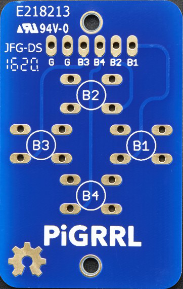
The PiGrrl Zero Custom Gamepad PCB is an electronic component designed by Adafruit, part of the PiGrrl Zero project, which enables enthusiasts to build their own handheld retro gaming device. This PCB simplifies the process of connecting buttons and a directional pad to a Raspberry Pi Zero, which acts as the computing core of the gaming system. The PiGrrl Zero project is a DIY homage to classic gaming consoles, allowing users to play old-school games through emulation.
Explore Projects Built with PiGrrl Zero Custom Gamepad PCB
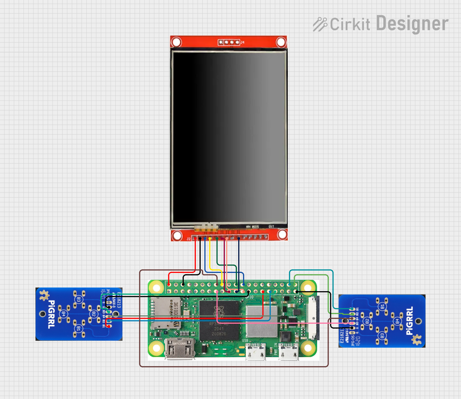

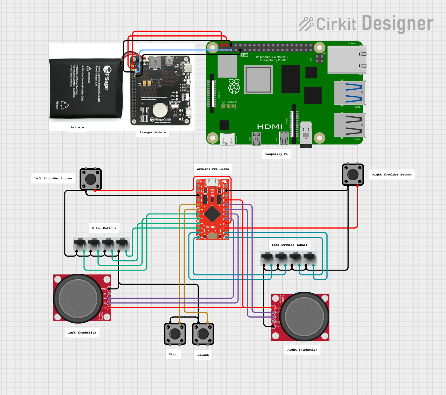
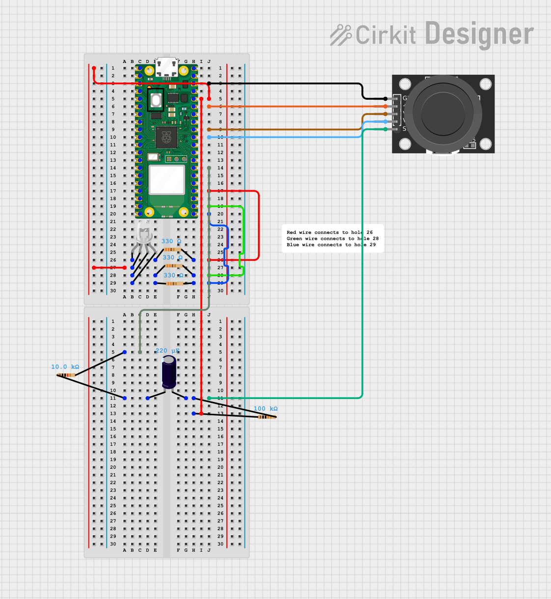
Explore Projects Built with PiGrrl Zero Custom Gamepad PCB
Common Applications and Use Cases
- DIY handheld gaming devices
- Educational projects for learning about electronics and gaming hardware
- Custom controllers for Raspberry Pi-based gaming systems
Technical Specifications
Key Technical Details
- Voltage: 3.3V - 5V (Typically powered by the Raspberry Pi Zero)
- Current: Dependent on button usage (minimal)
- Power Ratings: Low power consumption
Pin Configuration and Descriptions
| Pin Number | Description | Notes |
|---|---|---|
| 1 | Up Button | Connects to GPIO on Raspberry Pi |
| 2 | Down Button | Connects to GPIO on Raspberry Pi |
| 3 | Left Button | Connects to GPIO on Raspberry Pi |
| 4 | Right Button | Connects to GPIO on Raspberry Pi |
| 5 | A Button | Connects to GPIO on Raspberry Pi |
| 6 | B Button | Connects to GPIO on Raspberry Pi |
| 7 | X Button | Connects to GPIO on Raspberry Pi |
| 8 | Y Button | Connects to GPIO on Raspberry Pi |
| 9 | Start Button | Connects to GPIO on Raspberry Pi |
| 10 | Select Button | Connects to GPIO on Raspberry Pi |
| 11 | Ground | Common ground for all buttons |
Usage Instructions
How to Use the Component in a Circuit
- Connect the Buttons: Solder tactile buttons to the designated pads on the PCB.
- Connect to Raspberry Pi Zero: Use jumper wires to connect the button pads to the corresponding GPIO pins on the Raspberry Pi Zero.
- Grounding: Ensure that the ground pin on the PCB is connected to one of the ground pins on the Raspberry Pi Zero.
- Software Configuration: Configure the Raspberry Pi's software to recognize the button inputs. This typically involves setting up game emulation software and mapping the GPIO pins to specific controls.
Important Considerations and Best Practices
- Debouncing: Implement software debouncing to prevent false button press detections due to the mechanical nature of the buttons.
- Power Supply: Ensure that the Raspberry Pi Zero is adequately powered; insufficient power can lead to erratic behavior of the gamepad.
- GPIO Protection: Consider using resistors to protect the GPIO pins from potential overcurrent conditions.
Troubleshooting and FAQs
Common Issues Users Might Face
- Buttons Not Responding: Check the solder joints for cold solder or bridges between contacts. Ensure that the GPIO pins are correctly mapped in the software.
- Intermittent Button Response: This could be due to poor connections or the need for debouncing in the software.
- Pi Not Recognizing Inputs: Verify that the Raspberry Pi's GPIO pins are configured correctly and that the software is properly set up to read the button presses.
Solutions and Tips for Troubleshooting
- Check Connections: Re-solder any suspect connections and ensure that all wires are securely attached.
- Software Configuration: Double-check the software settings and ensure that the GPIO pins are mapped to the correct buttons.
- Reboot the Pi: Sometimes, simply rebooting the Raspberry Pi can resolve temporary issues.
Example Code for Arduino UNO
While the PiGrrl Zero Custom Gamepad PCB is designed for use with the Raspberry Pi Zero, it can also be interfaced with an Arduino UNO for other types of projects. Below is an example code snippet for reading button presses on an Arduino UNO.
// Define button pin constants
const int buttonUp = 2;
const int buttonDown = 3;
const int buttonLeft = 4;
const int buttonRight = 5;
// ... Define other buttons accordingly

void setup() {
  // Initialize button input pins
  pinMode(buttonUp, INPUT_PULLUP);
  pinMode(buttonDown, INPUT_PULLUP);
  pinMode(buttonLeft, INPUT_PULLUP);
  pinMode(buttonRight, INPUT_PULLUP);
  // ... Initialize other buttons accordingly
}

void loop() {
  // Read button states
  bool upPressed = !digitalRead(buttonUp);
  bool downPressed = !digitalRead(buttonDown);
  bool leftPressed = !digitalRead(buttonLeft);
  bool rightPressed = !digitalRead(buttonRight);
  // ... Read other buttons accordingly

  // Implement button functionality
  // For example, print button state to serial monitor
  if (upPressed) {
    Serial.println("Up button pressed");
  }
  // ... Implement other button functionalities accordingly

  // Small delay to debounce
  delay(50);
}
Remember to keep the code comments concise and within the 80 character line length limit. This example assumes the use of the Arduino's internal pull-up resistors, which is why the button states are inverted (!digitalRead(buttonPin)).
For further assistance or questions, users are encouraged to reach out to the Adafruit support forums or the Raspberry Pi community forums.