How to Use Voltage Regulator - Variable: Examples, Pinouts, and Specs
Introduction
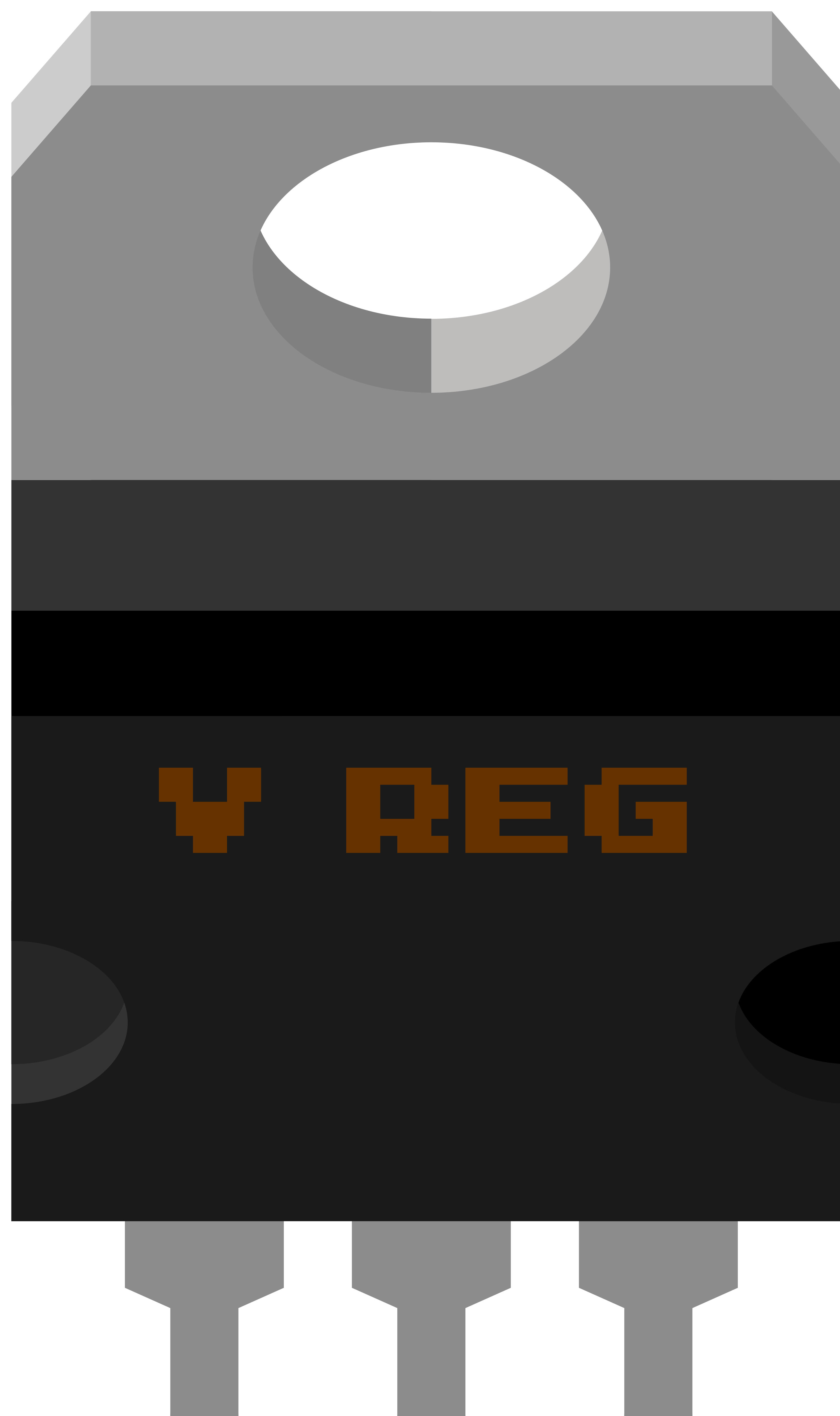
A variable voltage regulator is a versatile electronic component designed to maintain a constant output voltage level that can be adjusted as needed. This type of regulator is essential in applications where precise voltage control is necessary to protect sensitive electronic components or to ensure consistent performance. Common applications include power supplies, battery chargers, and as part of the voltage regulation in consumer electronics, such as computers and audio equipment.
Explore Projects Built with Voltage Regulator - Variable


Explore Projects Built with Voltage Regulator - Variable
Technical Specifications
Key Technical Details
- Input Voltage Range: The range of input voltages the regulator can handle.
- Output Voltage Range: The adjustable range of output voltages the regulator can provide.
- Output Current: Maximum current the regulator can supply.
- Temperature Range: Operating temperature range of the device.
- Efficiency: The ratio of output power to input power, typically expressed as a percentage.
- Load Regulation: The change in output voltage with varying load conditions.
- Line Regulation: The change in output voltage with varying input voltage.
- Thermal Protection: Indicates whether the device has built-in protection against overheating.
Pin Configuration and Descriptions
| Pin Number | Name | Description |
|---|---|---|
| 1 | ADJ | Adjustment pin used to set the output voltage |
| 2 | OUT | Regulated output voltage |
| 3 | IN | Input voltage |
Usage Instructions
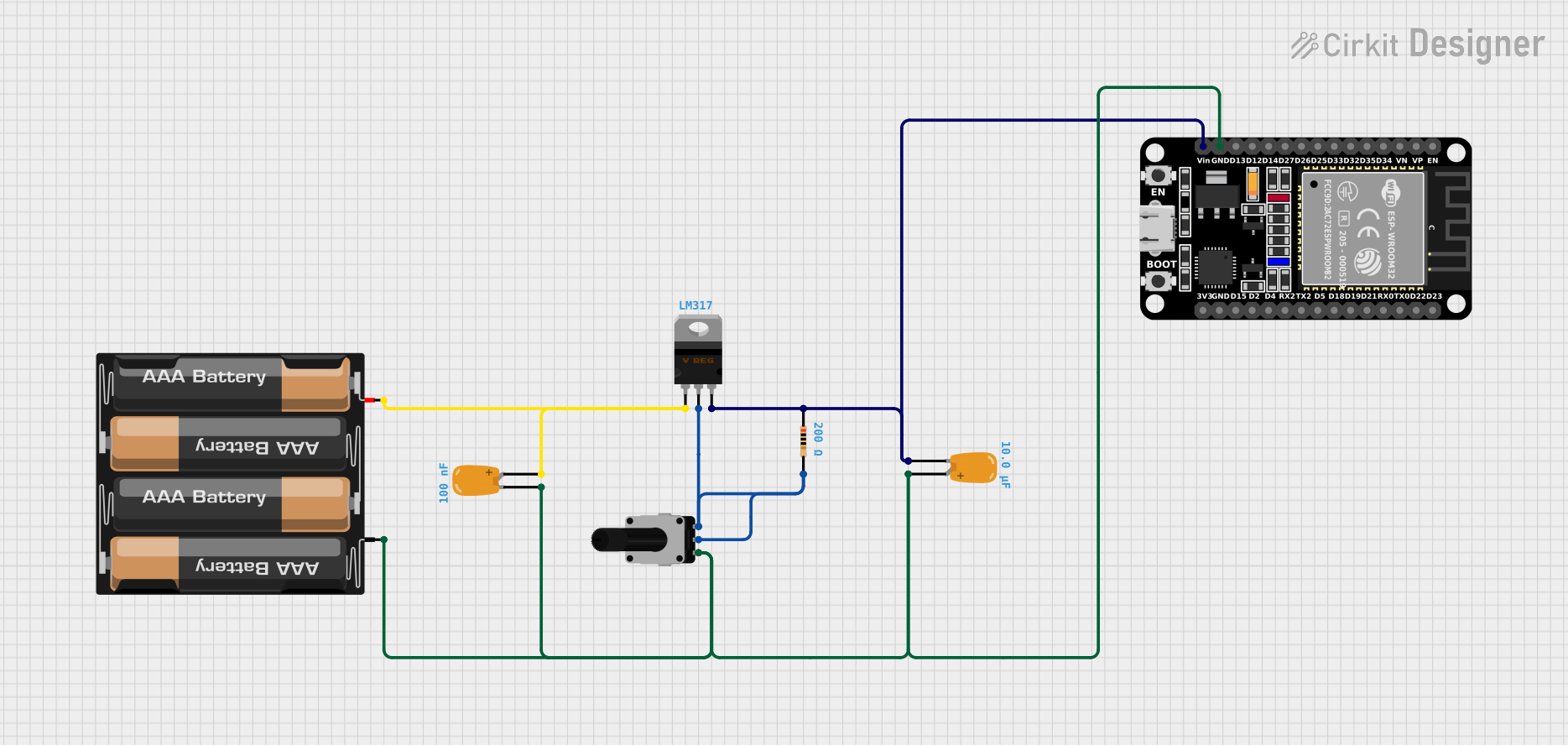
Incorporating into a Circuit
- Input Voltage: Connect a DC voltage source to the IN pin, ensuring it is within the specified input voltage range.
- Output Voltage Setting: Connect a variable resistor or a potentiometer between the ADJ and OUT pins to set the desired output voltage.
- Output Connection: Connect the load to the OUT pin, making sure the current draw does not exceed the maximum output current rating.
- Grounding: Connect the ground of your circuit to the ground reference of the voltage regulator.
Best Practices
- Use capacitors at the input and output for stability. Typically, a 0.1µF ceramic capacitor on the input and a 1µF electrolytic capacitor on the output are recommended.
- Ensure adequate heat sinking if the regulator is expected to dissipate significant power.
- Avoid placing high inductive loads directly at the output to prevent voltage spikes.
- Keep the adjustment pin connection as short as possible to avoid noise and voltage drops.
Example Code for Arduino UNO
// Example code to control a variable voltage regulator with an Arduino UNO
// The Arduino can't directly control the regulator's voltage, but it can
// control a digital potentiometer or a DAC connected to the ADJ pin.

#include <Wire.h> // Include the Wire library for I2C communication

// Define the I2C address for the digital potentiometer or DAC
#define POT_ADDRESS 0x2C

void setup() {
  Wire.begin(); // Start the I2C bus
  Serial.begin(9600); // Start serial communication for debugging
}

void loop() {
  // Set the desired voltage level by writing to the digital potentiometer
  // Replace 'desiredVoltageLevel' with the appropriate value
  int desiredVoltageLevel = 128; // Mid-scale value as an example
  setVoltage(desiredVoltageLevel);
  delay(1000); // Wait for 1 second
}

// Function to write to the digital potentiometer or DAC
void setVoltage(int level) {
  Wire.beginTransmission(POT_ADDRESS); // Begin transmission to the device
  Wire.write((byte)level); // Send the desired level
  Wire.endTransmission(); // End transmission
  Serial.print("Voltage level set to: ");
  Serial.println(level);
}
Troubleshooting and FAQs
Common Issues
- Output Voltage Not Adjusting: Ensure the adjustment pin is correctly connected and the variable resistor is functioning.
- Overheating: Check if the input voltage is too high or if the load is drawing too much current. Add a heat sink if necessary.
- Output Voltage Fluctuations: Verify that the input and output capacitors are in place and that the load is stable.
Solutions and Tips
- If the output voltage is not stable, check the connections to the ADJ pin and ensure there is no excessive resistance in the path.
- For thermal issues, improve airflow around the regulator or reduce the input voltage to lower the power dissipation.
- Always consult the datasheet for specific recommendations on capacitor types and values.
FAQs
Q: Can I use a fixed resistor instead of a variable one to set the output voltage? A: Yes, you can use a fixed resistor or a combination of resistors to set a specific output voltage.
Q: What happens if I exceed the maximum input voltage? A: Exceeding the maximum input voltage can damage the regulator. Always stay within the recommended voltage range.
Q: How do I calculate the heat sink size for my voltage regulator? A: Calculate the power dissipation (P = V * I) and consult the regulator's datasheet for thermal resistance information. Use this to determine the appropriate heat sink size.
Remember, this documentation is a starting point. Always refer to the manufacturer's datasheet for the most accurate and detailed information on using a variable voltage regulator.