How to Use Switch, Relay, 2 channel: Examples, Pinouts, and Specs
Introduction
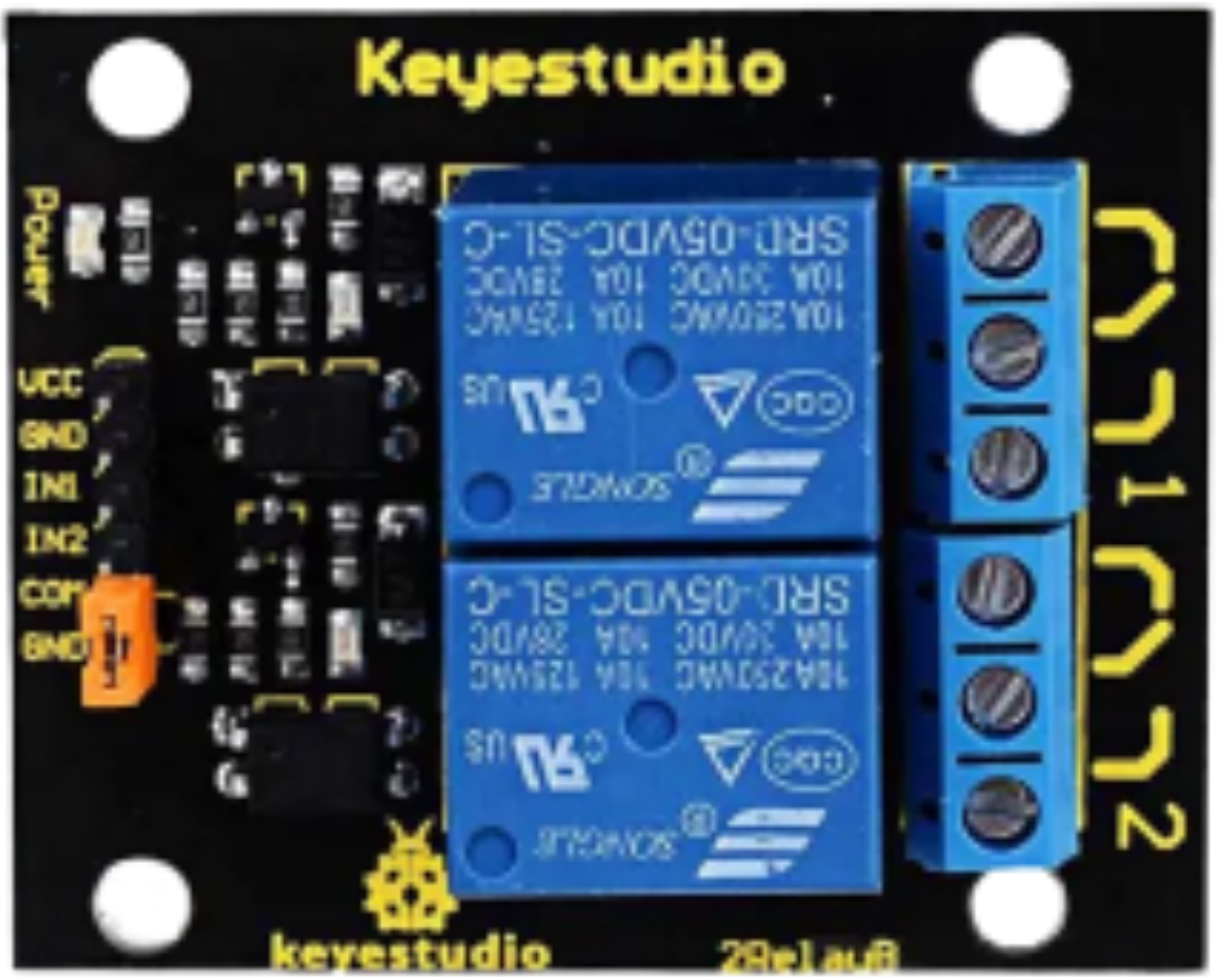
The 2-channel relay module is an electronic component designed to control high-voltage or high-current devices using low-power control signals. It acts as an electrically operated switch, allowing microcontrollers like Arduino, Raspberry Pi, or other digital systems to safely interface with devices such as lights, motors, or appliances.
This module is commonly used in home automation, industrial control systems, and robotics projects. Its ability to isolate the control circuit from the high-power circuit ensures safety and reliability in various applications.
Explore Projects Built with Switch, Relay, 2 channel


Explore Projects Built with Switch, Relay, 2 channel
Technical Specifications
- Relay Type: Electromechanical
- Number of Channels: 2
- Control Voltage: 5V DC
- Trigger Type: Active Low
- Maximum Load:
- AC: 250V at 10A
- DC: 30V at 10A
- Isolation: Optocoupler-based
- Dimensions: ~50mm x 40mm x 18mm
- Weight: ~30g
Pin Configuration and Descriptions
Input Pins
| Pin Name | Description |
|---|---|
| VCC | Connect to the 5V power supply of the control circuit. |
| GND | Connect to the ground of the control circuit. |
| IN1 | Control signal for Relay 1 (Active Low). |
| IN2 | Control signal for Relay 2 (Active Low). |
Output Terminals (for each relay)
| Terminal Name | Description |
|---|---|
| COM | Common terminal for the relay. Connect to the power source or load. |
| NO | Normally Open terminal. Connect to the load if it should be off by default. |
| NC | Normally Closed terminal. Connect to the load if it should be on by default. |
Usage Instructions
How to Use the Component in a Circuit
- Power the Module: Connect the VCC pin to a 5V power supply and the GND pin to the ground of your control circuit.
- Connect the Control Signals:
- Use digital output pins from a microcontroller (e.g., Arduino) to control IN1 and IN2.
- When the control signal is LOW, the corresponding relay will activate.
- Connect the Load:
- Identify whether your load should be connected to the Normally Open (NO) or Normally Closed (NC) terminal.
- Connect the power source to the COM terminal and the load to either NO or NC, depending on your requirements.
- Test the Circuit:
- Upload the control code to your microcontroller and verify the relay operation.
Important Considerations and Best Practices
- Isolation: Ensure proper isolation between the low-voltage control circuit and the high-voltage load circuit.
- Power Ratings: Do not exceed the maximum voltage or current ratings of the relay.
- Flyback Diode: If controlling inductive loads (e.g., motors), use a flyback diode across the load to protect the relay from voltage spikes.
- Active Low Trigger: Remember that the relay activates when the control signal is LOW.
Example Code for Arduino UNO
// Example code to control a 2-channel relay module with Arduino UNO

// Define the relay control pins
const int relay1 = 7; // Pin connected to IN1
const int relay2 = 8; // Pin connected to IN2

void setup() {
  // Set relay pins as outputs
  pinMode(relay1, OUTPUT);
  pinMode(relay2, OUTPUT);

  // Initialize relays to OFF state (HIGH signal)
  digitalWrite(relay1, HIGH); // Relay 1 off
  digitalWrite(relay2, HIGH); // Relay 2 off
}

void loop() {
  // Turn on Relay 1
  digitalWrite(relay1, LOW); // Activate Relay 1
  delay(2000);               // Wait for 2 seconds

  // Turn off Relay 1 and turn on Relay 2
  digitalWrite(relay1, HIGH); // Deactivate Relay 1
  digitalWrite(relay2, LOW);  // Activate Relay 2
  delay(2000);                // Wait for 2 seconds

  // Turn off both relays
  digitalWrite(relay1, HIGH); // Deactivate Relay 1
  digitalWrite(relay2, HIGH); // Deactivate Relay 2
  delay(2000);                // Wait for 2 seconds
}
Troubleshooting and FAQs
Common Issues
Relay Not Activating:
- Cause: Insufficient power supply to the module.
- Solution: Ensure the VCC pin is connected to a stable 5V source and the GND pin is properly grounded.
Relay Stuck in ON or OFF State:
- Cause: Incorrect wiring or damaged relay.
- Solution: Double-check the wiring and ensure the control signals are correctly applied.
Microcontroller Resetting When Relay Activates:
- Cause: Voltage spikes from the load affecting the control circuit.
- Solution: Use a flyback diode across inductive loads and ensure proper grounding.
Load Not Turning On/Off:
- Cause: Incorrect connection to the NO/NC terminals.
- Solution: Verify the load is connected to the correct terminal (NO or NC) based on your requirements.
FAQs
Can I use this module with a 3.3V microcontroller?
- Yes, but you may need a level shifter or transistor circuit to ensure proper triggering of the relay.
Is the relay module safe for AC appliances?
- Yes, as long as the voltage and current ratings of the relay are not exceeded.
Can I control both relays simultaneously?
- Yes, you can activate both relays at the same time by setting both control signals to LOW.
What is the lifespan of the relay?
- The relay typically has a mechanical lifespan of 100,000 operations under normal conditions.