Cirkit Designer Logo
Cirkit Designer
Your all-in-one circuit design IDE
Home / 
Component Documentation

How to Use 74LS32: Examples, Pinouts, and Specs

Image of 74LS32
Cirkit Designer LogoDesign with 74LS32 in Cirkit Designer

Introduction

The 74LS32 is a quad 2-input OR gate that provides four independent OR functions. It belongs to the Low Power Schottky TTL (Transistor-Transistor Logic) family, which is known for its fast switching times and low power consumption. This component is widely used in digital circuits for implementing logical operations, signal routing, and data processing.

Explore Projects Built with 74LS32

Use Cirkit Designer to design, explore, and prototype these projects online. Some projects support real-time simulation. Click "Open Project" to start designing instantly!
Logic Gate Experimentation Board with DIP Switch Control and LED Indicators
Image of Lab 4 Encoder: A project utilizing 74LS32 in a practical application
This circuit is a digital logic demonstration setup using a 3-position DIP switch to control the logic states of a series of gates (inverters, AND, and OR) from the 74HC logic family. The output of these gates is used to drive three LEDs through current-limiting resistors, indicating the logic levels after processing by the gates. The circuit is powered by a DC power source, with all ICs sharing a common ground and VCC.
Cirkit Designer LogoOpen Project in Cirkit Designer
Digital Logic State Indicator with Flip-Flops and Logic Gates
Image of 2-bit Gray Code Counter: A project utilizing 74LS32 in a practical application
This circuit is a digital logic system that uses a DIP switch to provide input to a network of flip-flops and logic gates, which process the input signals. The output of this processing is likely indicated by LEDs, which are connected through resistors to limit current. The circuit functions autonomously without a microcontroller, relying on the inherent properties of the digital components to perform its logic operations.
Cirkit Designer LogoOpen Project in Cirkit Designer
A-Star 32U4 Mini Controlled LED Strip Lighting
Image of Tira LED: A project utilizing 74LS32 in a practical application
This circuit consists of an A-Star 32U4 Mini microcontroller connected to an LED Strip. The microcontroller provides power (5V) and ground connections to the LED Strip and controls it through two digital pins (12 and 11) for clock (CI) and data input (DI), respectively. The purpose of this circuit is to enable the microcontroller to control the lighting patterns or colors of the LED Strip.
Cirkit Designer LogoOpen Project in Cirkit Designer
ESP32 and Logic Level Converter-Based Wi-Fi Controlled Interface
Image of Toshiba AC ESP32 devkit v1: A project utilizing 74LS32 in a practical application
This circuit features an ESP32 Devkit V1 microcontroller connected to a Bi-Directional Logic Level Converter, which facilitates voltage level shifting between the ESP32 and external components. The ESP32 is powered through its VIN pin via an alligator clip cable, and the logic level converter is connected to various pins on the ESP32 to manage different voltage levels for communication.
Cirkit Designer LogoOpen Project in Cirkit Designer

Explore Projects Built with 74LS32

Use Cirkit Designer to design, explore, and prototype these projects online. Some projects support real-time simulation. Click "Open Project" to start designing instantly!
Image of Lab 4 Encoder: A project utilizing 74LS32 in a practical application
Logic Gate Experimentation Board with DIP Switch Control and LED Indicators
This circuit is a digital logic demonstration setup using a 3-position DIP switch to control the logic states of a series of gates (inverters, AND, and OR) from the 74HC logic family. The output of these gates is used to drive three LEDs through current-limiting resistors, indicating the logic levels after processing by the gates. The circuit is powered by a DC power source, with all ICs sharing a common ground and VCC.
Cirkit Designer LogoOpen Project in Cirkit Designer
Image of 2-bit Gray Code Counter: A project utilizing 74LS32 in a practical application
Digital Logic State Indicator with Flip-Flops and Logic Gates
This circuit is a digital logic system that uses a DIP switch to provide input to a network of flip-flops and logic gates, which process the input signals. The output of this processing is likely indicated by LEDs, which are connected through resistors to limit current. The circuit functions autonomously without a microcontroller, relying on the inherent properties of the digital components to perform its logic operations.
Cirkit Designer LogoOpen Project in Cirkit Designer
Image of Tira LED: A project utilizing 74LS32 in a practical application
A-Star 32U4 Mini Controlled LED Strip Lighting
This circuit consists of an A-Star 32U4 Mini microcontroller connected to an LED Strip. The microcontroller provides power (5V) and ground connections to the LED Strip and controls it through two digital pins (12 and 11) for clock (CI) and data input (DI), respectively. The purpose of this circuit is to enable the microcontroller to control the lighting patterns or colors of the LED Strip.
Cirkit Designer LogoOpen Project in Cirkit Designer
Image of Toshiba AC ESP32 devkit v1: A project utilizing 74LS32 in a practical application
ESP32 and Logic Level Converter-Based Wi-Fi Controlled Interface
This circuit features an ESP32 Devkit V1 microcontroller connected to a Bi-Directional Logic Level Converter, which facilitates voltage level shifting between the ESP32 and external components. The ESP32 is powered through its VIN pin via an alligator clip cable, and the logic level converter is connected to various pins on the ESP32 to manage different voltage levels for communication.
Cirkit Designer LogoOpen Project in Cirkit Designer

Common Applications and Use Cases

  • Digital Logic Circuits: Used in combinational logic designs.
  • Signal Processing: Combines multiple signals into a single output.
  • Data Routing: Directs data flow in multiplexers and demultiplexers.
  • Control Systems: Implements logical conditions in control applications.

Technical Specifications

Key Technical Details

Parameter Value
Supply Voltage (Vcc) 4.75V to 5.25V
Input Voltage (VIH) 2.0V (minimum high level)
Input Voltage (VIL) 0.8V (maximum low level)
Output Voltage (VOH) 2.7V (minimum high level)
Output Voltage (VOL) 0.4V (maximum low level)
Maximum Output Current 6 mA
Power Dissipation 1.0 W (max)
Operating Temperature -40°C to +85°C

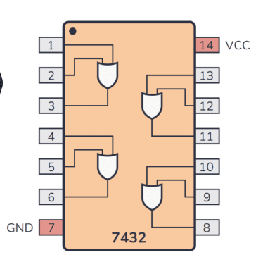
Pin Configuration and Descriptions

Pin Number Pin Name Description
1 A1 Input A for OR gate 1
2 B1 Input B for OR gate 1
3 Y1 Output for OR gate 1
4 A2 Input A for OR gate 2
5 B2 Input B for OR gate 2
6 Y2 Output for OR gate 2
7 GND Ground connection
8 Y3 Output for OR gate 3
9 A3 Input A for OR gate 3
10 B3 Input B for OR gate 3
11 Y4 Output for OR gate 4
12 A4 Input A for OR gate 4
13 B4 Input B for OR gate 4
14 Vcc Supply voltage connection

Usage Instructions

How to Use the Component in a Circuit

  1. Power Supply: Connect the Vcc pin (14) to a +5V power supply and the GND pin (7) to ground.
  2. Input Connections: Connect your input signals to the appropriate A and B pins (1, 2 for gate 1, 4, 5 for gate 2, etc.).
  3. Output Connections: Connect the output pins (3, 6, 8, 11) to the next stage of your circuit.

Important Considerations and Best Practices

  • Ensure that the supply voltage is within the specified range (4.75V to 5.25V).
  • Avoid exceeding the maximum output current rating (6 mA) to prevent damage.
  • Use pull-up or pull-down resistors if necessary to ensure stable input levels.
  • Keep the circuit layout compact to minimize noise and interference.

Troubleshooting and FAQs

Common Issues Users Might Face

  1. No Output Signal:

    • Check power supply connections (Vcc and GND).
    • Verify that input signals are within the specified voltage levels.
  2. Incorrect Output:

    • Ensure that the inputs are connected correctly.
    • Check for short circuits or faulty connections.
  3. Overheating:

    • Ensure that the component is not exceeding the maximum power dissipation.
    • Check for excessive load on the output pins.

Solutions and Tips for Troubleshooting

  • Use a multimeter to measure voltage levels at the input and output pins.
  • Inspect the circuit for loose connections or soldering issues.
  • If using a breadboard, ensure that the component is seated properly.

Example Code for Arduino UNO

If you are using the 74LS32 with an Arduino UNO, you can control the OR gates using digital pins. Below is a simple example code that demonstrates how to use the 74LS32 in an Arduino project.

// Define pin connections
const int inputA1 = 2; // A1 connected to pin 2
const int inputB1 = 3; // B1 connected to pin 3
const int outputY1 = 4; // Y1 connected to pin 4

void setup() {
  // Set pin modes
  pinMode(inputA1, INPUT);
  pinMode(inputB1, INPUT);
  pinMode(outputY1, OUTPUT);
}

void loop() {
  // Read inputs
  int a = digitalRead(inputA1);
  int b = digitalRead(inputB1);
  
  // Perform OR operation
  int result = a | b;
  
  // Set output
  digitalWrite(outputY1, result);
  
  // Small delay for stability
  delay(100);
}

This code reads the inputs connected to A1 and B1, performs the OR operation, and sets the output Y1 accordingly. Make sure to connect the inputs to the appropriate pins on the Arduino UNO.