How to Use tower lamp: Examples, Pinouts, and Specs
Introduction
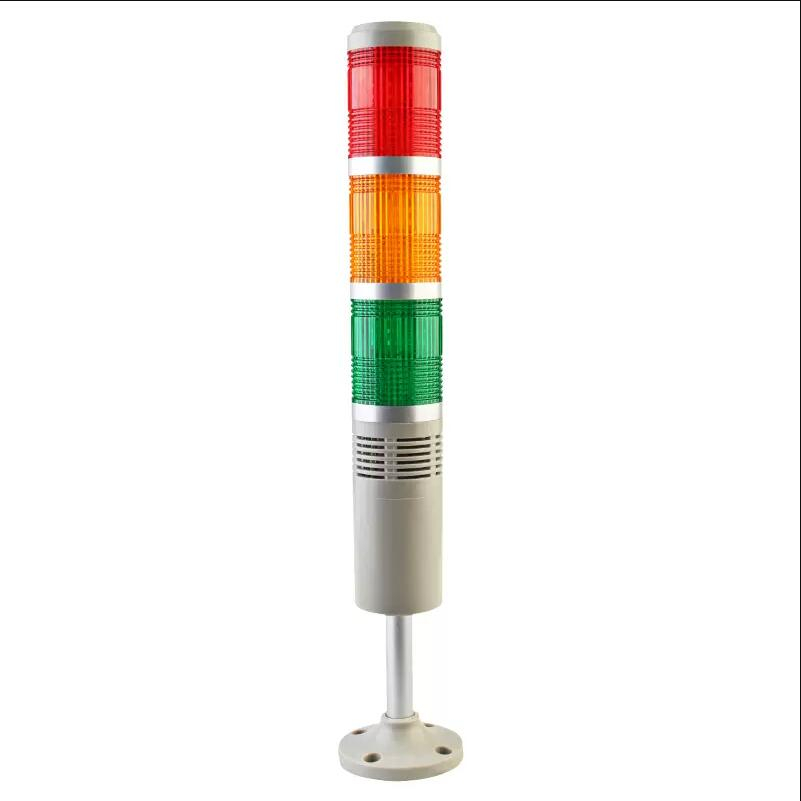
A tower lamp, also known as a signal tower or stack light, is a multi-segmented light fixture commonly used in industrial settings. It provides visual signals indicating the status of machinery or processes. Each segment of the tower lamp can light up in different colors to convey various messages, such as operational status, warnings, or errors. This makes it an essential component for ensuring safety and efficiency in industrial environments.
Explore Projects Built with tower lamp
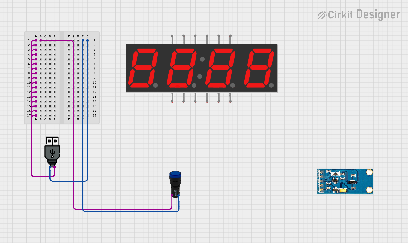


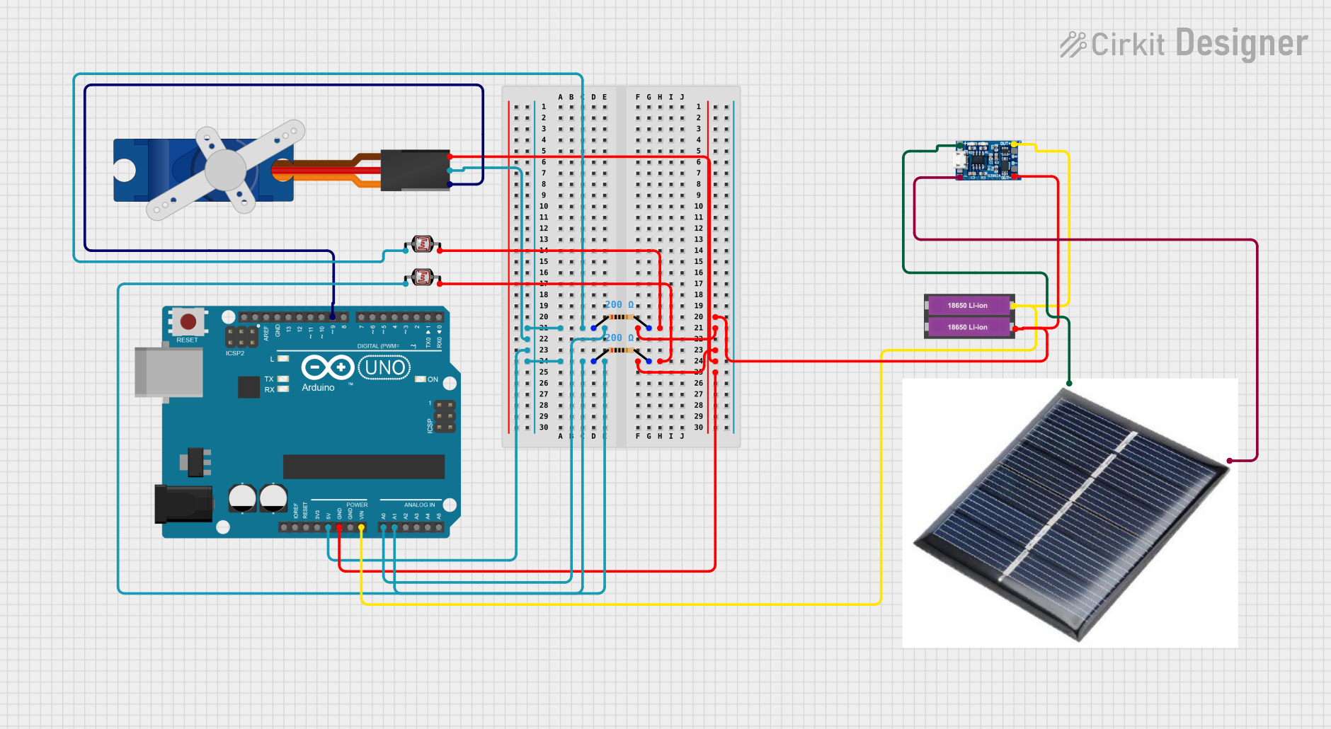
Explore Projects Built with tower lamp
Technical Specifications
Key Technical Details
| Parameter | Value |
|---|---|
| Operating Voltage | 24V DC |
| Current Consumption | 20mA per segment |
| Power Rating | 0.48W per segment |
| Number of Segments | 3 to 5 (depending on model) |
| Light Colors | Red, Yellow, Green, Blue, White |
| Mounting Type | Pole or base-mounted |
| IP Rating | IP54 |
Pin Configuration and Descriptions
| Pin Number | Description | Color Code (if applicable) |
|---|---|---|
| 1 | Ground (GND) | Black |
| 2 | Power Supply (24V DC) | Red |
| 3 | Control Signal for Red | Brown |
| 4 | Control Signal for Yellow | Yellow |
| 5 | Control Signal for Green | Green |
| 6 | Control Signal for Blue | Blue |
| 7 | Control Signal for White | White |
Usage Instructions
How to Use the Component in a Circuit
Power Supply Connection:
- Connect the
Ground (GND)pin to the ground of your power supply. - Connect the
Power Supply (24V DC)pin to the 24V DC output of your power supply.
- Connect the
Control Signals:
- Each segment of the tower lamp is controlled by a separate signal pin.
- To light up a segment, apply a control signal (typically 24V DC) to the corresponding pin.
- For example, to light up the red segment, apply 24V DC to the
Control Signal for Redpin.
Important Considerations and Best Practices
- Voltage Compatibility: Ensure that the power supply voltage matches the operating voltage of the tower lamp (24V DC).
- Current Limiting: Use current-limiting resistors if necessary to prevent overcurrent conditions.
- Environmental Protection: The tower lamp has an IP54 rating, making it suitable for indoor use and protection against dust and splashing water. However, avoid using it in extremely wet or dusty environments.
- Mounting: Securely mount the tower lamp using the provided pole or base mount to prevent it from falling or being damaged.
Example: Connecting to an Arduino UNO
To control the tower lamp using an Arduino UNO, you can use digital output pins to send control signals to the lamp. Below is an example code to control a 3-segment tower lamp (Red, Yellow, Green).
// Pin definitions
const int redPin = 2;
const int yellowPin = 3;
const int greenPin = 4;

void setup() {
  // Initialize the digital pins as outputs
  pinMode(redPin, OUTPUT);
  pinMode(yellowPin, OUTPUT);
  pinMode(greenPin, OUTPUT);
}

void loop() {
  // Turn on the red segment
  digitalWrite(redPin, HIGH);
  delay(1000); // Wait for 1 second

  // Turn off the red segment and turn on the yellow segment
  digitalWrite(redPin, LOW);
  digitalWrite(yellowPin, HIGH);
  delay(1000); // Wait for 1 second

  // Turn off the yellow segment and turn on the green segment
  digitalWrite(yellowPin, LOW);
  digitalWrite(greenPin, HIGH);
  delay(1000); // Wait for 1 second

  // Turn off the green segment
  digitalWrite(greenPin, LOW);
  delay(1000); // Wait for 1 second
}
Troubleshooting and FAQs
Common Issues Users Might Face
Segments Not Lighting Up:
- Solution: Check the power supply connections and ensure that the control signals are correctly applied to the corresponding pins.
Flickering Lights:
- Solution: Ensure that the power supply is stable and capable of providing the required current. Check for loose connections.
Incorrect Colors Lighting Up:
- Solution: Verify the pin connections and ensure that the control signals are applied to the correct pins.
FAQs
Q1: Can I use a different voltage power supply?
- A1: No, the tower lamp is designed to operate at 24V DC. Using a different voltage may damage the lamp.
Q2: How many segments can I control with an Arduino UNO?
- A2: The Arduino UNO has 14 digital I/O pins, so you can control up to 14 segments, but typically tower lamps have 3 to 5 segments.
Q3: Can I use PWM to control the brightness of the segments?
- A3: Yes, you can use PWM (Pulse Width Modulation) to control the brightness of the segments by connecting the control pins to PWM-capable pins on the Arduino.
By following this documentation, you should be able to effectively use and troubleshoot a tower lamp in your industrial applications.