
How to Use DS18b20 df robot: Examples, Pinouts, and Specs
 Design with DS18b20 df robot in Cirkit Designer
Introduction
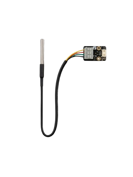
The DS18B20 is a digital temperature sensor manufactured by DFRobot, designed for precise temperature measurement in a wide range of applications. This sensor communicates using the 1-Wire protocol, allowing multiple sensors to be connected to a single data line. It is widely used in weather monitoring systems, industrial temperature control, and home automation projects due to its accuracy and ease of use.
Explore Projects Built with DS18b20 df robot
 Open Project in Cirkit Designer
 Open Project in Cirkit Designer
 Open Project in Cirkit Designer
 Open Project in Cirkit Designer
Explore Projects Built with DS18b20 df robot
Open Project in Cirkit DesignerOpen Project in Cirkit DesignerOpen Project in Cirkit DesignerOpen Project in Cirkit DesignerCommon Applications
- Weather stations and environmental monitoring
- Industrial temperature control systems
- Home automation and HVAC systems
- Data logging and IoT projects
- Educational and prototyping purposes
Technical Specifications
The DS18B20 sensor offers reliable performance with the following key specifications:
| Parameter | Value |
|---|---|
| Operating Voltage | 3.0V to 5.5V |
| Temperature Range | -55°C to +125°C |
| Accuracy | ±0.5°C (from -10°C to +85°C) |
| Resolution | Programmable (9 to 12 bits) |
| Communication Protocol | 1-Wire |
| Maximum Current Draw | 1.5mA during conversion |
| Waterproof Version | Available (encased in stainless steel) |
Pin Configuration
The DS18B20 sensor typically has three pins. Below is the pinout description:
| Pin | Name | Description |
|---|---|---|
| 1 | GND | Ground connection |
| 2 | DQ | Data line for 1-Wire communication |
| 3 | VDD | Power supply (3.0V to 5.5V) |
Note: A 4.7kΩ pull-up resistor is required between the DQ pin and VDD for proper communication.
Usage Instructions
Connecting the DS18B20 to a Circuit
- Power Supply: Connect the VDD pin to a 3.3V or 5V power source and the GND pin to ground.
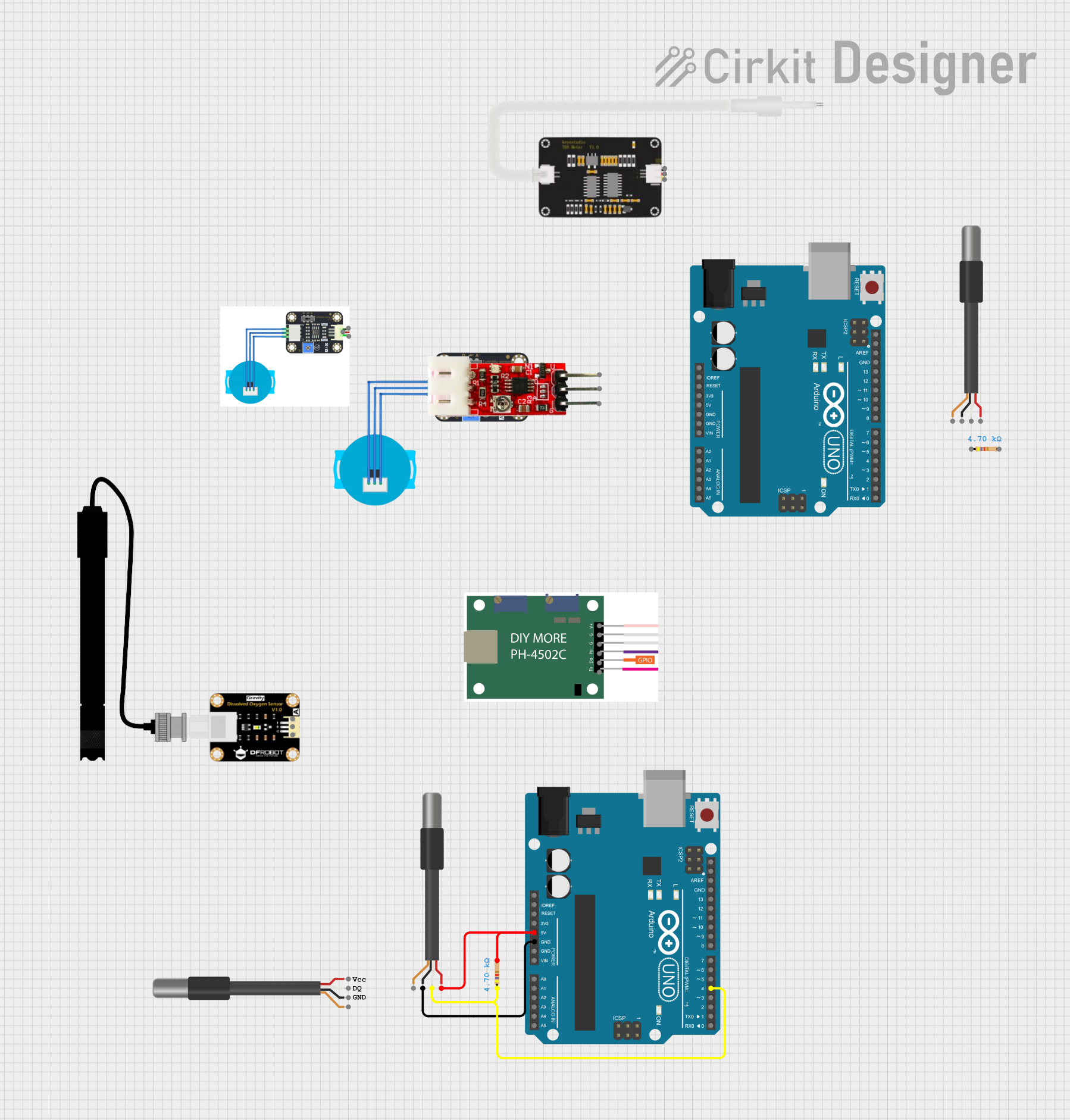
- Data Line: Connect the DQ pin to a digital I/O pin on your microcontroller (e.g., Arduino UNO). Add a 4.7kΩ pull-up resistor between the DQ pin and VDD.
- Multiple Sensors: If using multiple DS18B20 sensors, connect all DQ pins to the same data line. Each sensor has a unique 64-bit address for identification.
Arduino UNO Example Code
Below is an example of how to use the DS18B20 with an Arduino UNO. This code reads the temperature and displays it on the Serial Monitor.
#include <OneWire.h>
#include <DallasTemperature.h>

// Pin connected to the DS18B20 data line
#define ONE_WIRE_BUS 2

// Setup a oneWire instance to communicate with any 1-Wire devices
OneWire oneWire(ONE_WIRE_BUS);

// Pass the oneWire reference to DallasTemperature library
DallasTemperature sensors(&oneWire);

void setup() {
  Serial.begin(9600); // Initialize serial communication
  sensors.begin();    // Start the DS18B20 sensor
  Serial.println("DS18B20 Temperature Sensor Initialized");
}

void loop() {
  sensors.requestTemperatures(); // Send command to get temperature readings
  float temperatureC = sensors.getTempCByIndex(0); // Get temperature in Celsius
  if (temperatureC != DEVICE_DISCONNECTED_C) {
    Serial.print("Temperature: ");
    Serial.print(temperatureC);
    Serial.println(" °C");
  } else {
    Serial.println("Error: Sensor not detected!");
  }
  delay(1000); // Wait 1 second before the next reading
}
Best Practices
- Use a waterproof version of the DS18B20 for outdoor or liquid temperature measurements.
- Ensure the pull-up resistor is correctly connected to avoid communication errors.
- Avoid long data lines to minimize signal degradation; use shielded cables if necessary.
- For multiple sensors, ensure each sensor's unique address is used for identification.
Troubleshooting and FAQs
Common Issues
Sensor Not Detected:
- Ensure the pull-up resistor is connected between the DQ pin and VDD.
- Verify the wiring and connections.
- Check the power supply voltage (3.0V to 5.5V).
Incorrect Temperature Readings:
- Ensure the sensor is not exposed to conditions beyond its operating range.
- Verify the resolution setting in the code (default is 12-bit).
Intermittent Communication:
- Use shorter wires or shielded cables to reduce noise.
- Check for loose connections or damaged cables.
FAQs
Q: Can I use the DS18B20 with a 3.3V microcontroller?
A: Yes, the DS18B20 operates within a voltage range of 3.0V to 5.5V, making it compatible with 3.3V systems.
Q: How many DS18B20 sensors can I connect to a single data line?
A: Theoretically, you can connect up to 100 sensors on a single data line, but practical limitations like power supply and signal integrity may reduce this number.
Q: What is the purpose of the pull-up resistor?
A: The pull-up resistor ensures proper communication on the 1-Wire bus by keeping the data line at a high logic level when idle.
Q: Can the DS18B20 measure negative temperatures?
A: Yes, the DS18B20 can measure temperatures as low as -55°C.
By following this documentation, you can effectively integrate the DS18B20 sensor into your projects for accurate and reliable temperature measurements.