How to Use DC Contactor: Examples, Pinouts, and Specs
Introduction
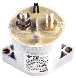
A DC contactor is an electromechanical switch designed to control high-voltage DC loads. Manufactured by Me, this component operates similarly to a relay but is specifically optimized for direct current applications. It provides reliable switching and isolation in circuits, making it an essential component in various industrial and automotive systems.
Explore Projects Built with DC Contactor

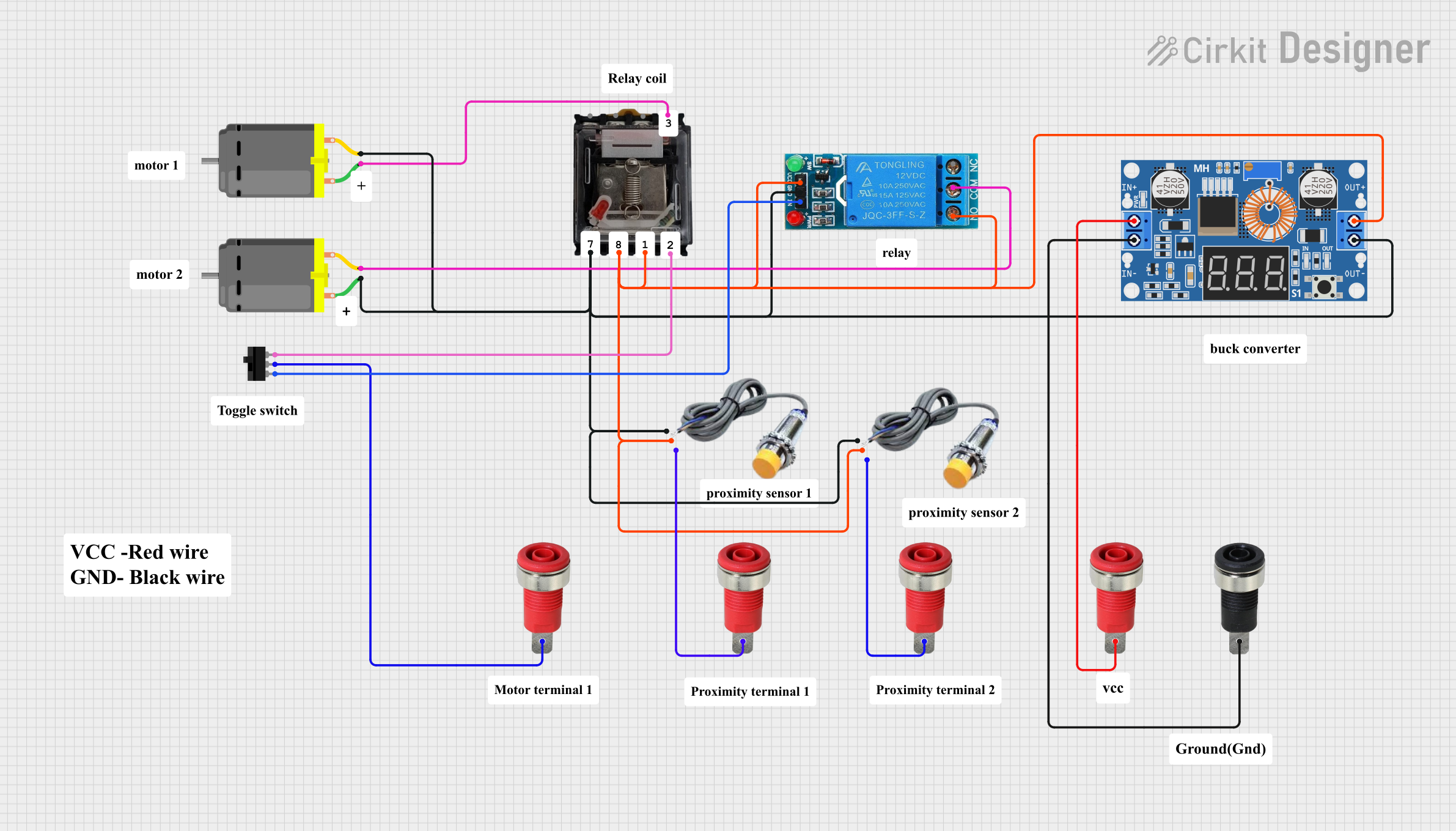

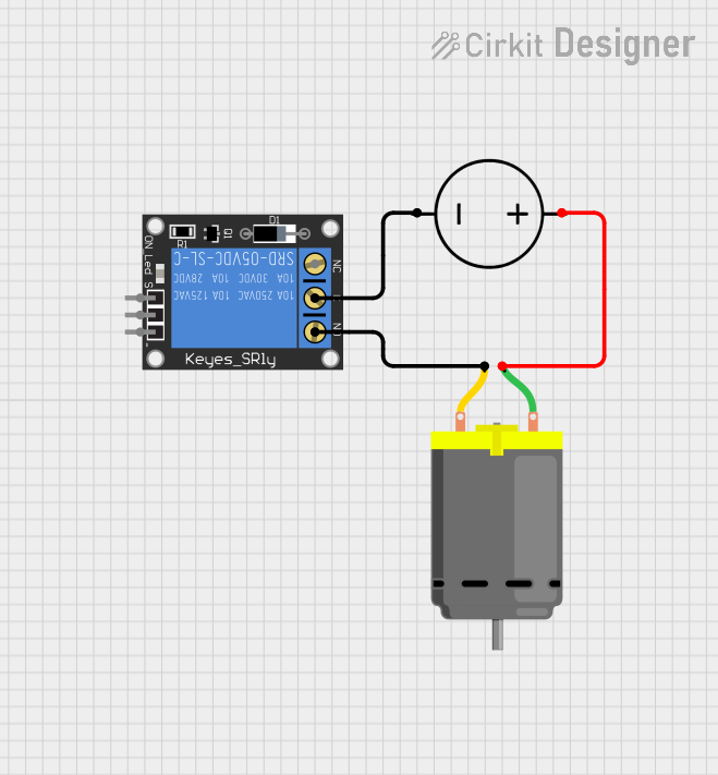
Explore Projects Built with DC Contactor
Common Applications and Use Cases
- Electric vehicle (EV) battery management systems
- Solar power systems and energy storage
- Industrial machinery and motor control
- High-voltage DC power distribution
- Uninterruptible power supplies (UPS)
Technical Specifications
Key Technical Details
| Parameter | Value |
|---|---|
| Operating Voltage Range | 12V DC to 1000V DC |
| Rated Current | 50A, 100A, 200A (varies by model) |
| Coil Voltage | 12V DC, 24V DC, or 48V DC |
| Contact Resistance | ≤ 0.5 mΩ |
| Insulation Resistance | ≥ 1000 MΩ |
| Mechanical Life | ≥ 1,000,000 operations |
| Electrical Life | ≥ 100,000 operations |
| Operating Temperature | -40°C to +85°C |
| Mounting Style | Panel mount |
Pin Configuration and Descriptions
| Pin Name | Description |
|---|---|
| Coil (+) | Positive terminal of the contactor's coil. Used to energize the contactor. |
| Coil (-) | Negative terminal of the contactor's coil. Completes the coil circuit. |
| Main Contact 1 | One side of the high-current switching contact. |
| Main Contact 2 | The other side of the high-current switching contact. |
| Auxiliary NC | Normally closed auxiliary contact for monitoring or control purposes. |
| Auxiliary NO | Normally open auxiliary contact for monitoring or control purposes. |
Usage Instructions
How to Use the DC Contactor in a Circuit
- Power the Coil: Connect the coil terminals (Coil (+) and Coil (-)) to a DC power source that matches the rated coil voltage (e.g., 12V DC, 24V DC, or 48V DC). Use a suitable driver circuit or relay to control the coil.
- Connect the Load: Wire the high-current load to the main contacts (Main Contact 1 and Main Contact 2). Ensure the load current does not exceed the rated current of the contactor.
- Auxiliary Contacts: Use the auxiliary contacts (NC or NO) for monitoring or control purposes, such as signaling the contactor's state to a microcontroller or PLC.
- Mounting: Secure the contactor to a panel or enclosure using the provided mounting holes. Ensure proper insulation and spacing from other components.
Important Considerations and Best Practices
- Voltage and Current Ratings: Always ensure the contactor's voltage and current ratings match the application requirements.
- Back-EMF Protection: When controlling the coil with a microcontroller or transistor, use a flyback diode across the coil terminals to suppress voltage spikes caused by inductive loads.
- Heat Dissipation: Ensure adequate ventilation or heat sinking to prevent overheating during prolonged operation.
- Polarity: Observe correct polarity when connecting the coil terminals to avoid damage.
- Pre-Charge Circuit: For high-voltage applications, consider using a pre-charge circuit to limit inrush current when the contactor closes.
Example: Controlling a DC Contactor with Arduino UNO
Below is an example of how to control a 12V DC contactor using an Arduino UNO and a transistor as a driver.
// Define the pin connected to the transistor's base
const int contactorPin = 9;

void setup() {
  pinMode(contactorPin, OUTPUT); // Set the pin as an output
}

void loop() {
  digitalWrite(contactorPin, HIGH); // Energize the contactor
  delay(5000); // Keep the contactor closed for 5 seconds

  digitalWrite(contactorPin, LOW); // De-energize the contactor
  delay(5000); // Wait for 5 seconds before repeating
}
Circuit Notes:
- Use an NPN transistor (e.g., 2N2222) to drive the contactor coil. Connect the transistor's collector to one side of the coil and the emitter to ground.
- Place a flyback diode (e.g., 1N4007) across the coil terminals to protect the transistor from voltage spikes.
- Use a base resistor (e.g., 1kΩ) between the Arduino pin and the transistor's base to limit current.
Troubleshooting and FAQs
Common Issues and Solutions
Contactor Does Not Energize:
- Verify the coil voltage matches the power supply.
- Check the connections to the coil terminals for proper polarity.
- Ensure the control circuit (e.g., Arduino or relay) is functioning correctly.
Excessive Heat:
- Ensure the contactor is not exceeding its rated current.
- Check for proper ventilation or heat sinking.
Arcing on Main Contacts:
- Verify the load does not exceed the contactor's voltage and current ratings.
- Consider using a snubber circuit to suppress arcing in high-voltage applications.
Auxiliary Contacts Not Working:
- Confirm the auxiliary contacts are wired correctly.
- Test the auxiliary contacts with a multimeter to ensure proper operation.
FAQs
Q: Can I use a DC contactor for AC loads?
A: No, DC contactors are specifically designed for direct current applications. For AC loads, use an AC contactor.
Q: How do I select the right DC contactor for my application?
A: Consider the operating voltage, current, coil voltage, and environmental conditions (e.g., temperature, humidity). Ensure the contactor's ratings exceed the maximum requirements of your application.
Q: What is the difference between a relay and a DC contactor?
A: While both are electromechanical switches, DC contactors are designed for higher current and voltage ratings, making them suitable for heavy-duty applications. Relays are typically used for lower-power circuits.
Q: Can I mount the contactor in any orientation?
A: Most DC contactors can be mounted in any orientation, but refer to the manufacturer's datasheet for specific recommendations.