
How to Use Conector Anderson red: Examples, Pinouts, and Specs
 Design with Conector Anderson red in Cirkit Designer
Introduction
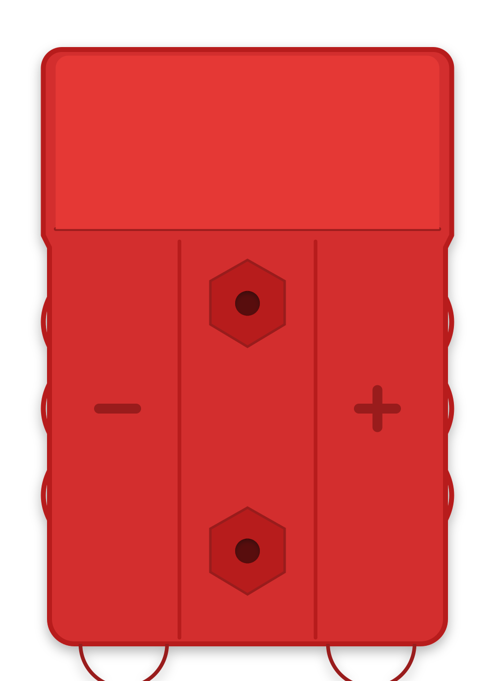
The Anderson Connector (Red) is a high-current, genderless connector designed for quick, secure, and reliable electrical connections. It is widely used in battery and power distribution applications due to its robust design and ease of use. The red color typically signifies a positive connection, making it ideal for applications where polarity identification is critical.
Explore Projects Built with Conector Anderson red
 Open Project in Cirkit Designer
 Open Project in Cirkit Designer
 Open Project in Cirkit Designer
 Open Project in Cirkit Designer
Explore Projects Built with Conector Anderson red
Open Project in Cirkit DesignerOpen Project in Cirkit DesignerOpen Project in Cirkit DesignerOpen Project in Cirkit DesignerCommon Applications and Use Cases
- Battery connections for electric vehicles, solar systems, and backup power supplies
- High-current DC power distribution in industrial and commercial equipment
- Robotics and RC (remote control) systems
- Quick-disconnect systems for portable devices and tools
Technical Specifications
The Anderson Connector (Red) is designed to handle high currents and voltages while maintaining a secure and low-resistance connection. Below are the key technical details:
| Parameter | Specification |
|---|---|
| Current Rating | Up to 50A (depending on wire gauge) |
| Voltage Rating | Up to 600V DC |
| Contact Material | Copper with silver or tin plating |
| Housing Material | Polycarbonate (PC) |
| Operating Temperature | -20°C to +105°C |
| Wire Gauge Compatibility | 6 AWG to 12 AWG |
| Mating Cycles | 10,000+ |
| Color | Red (typically indicates positive) |
Pin Configuration and Descriptions
The Anderson Connector (Red) is a genderless connector, meaning both sides of the connector are identical and can mate with each other. It consists of the following components:
| Pin/Part | Description |
|---|---|
| Positive Terminal | Designed to carry the positive DC voltage. Typically connected to the red wire. |
| Negative Terminal | Designed to carry the negative DC voltage. Typically connected to the black wire. |
| Housing | Durable polycarbonate shell that provides insulation and mechanical protection. |
| Retention Clips | Built-in clips to ensure a secure connection and prevent accidental disconnection. |
Usage Instructions
How to Use the Anderson Connector (Red) in a Circuit
Prepare the Wires:
- Strip the insulation from the wires to expose approximately 10-12mm of copper.
- Ensure the wire gauge matches the connector's specifications (6 AWG to 12 AWG).
Crimp the Contacts:
- Insert the stripped wire into the metal contact terminal.
- Use a proper crimping tool to securely crimp the contact onto the wire.
Insert Contacts into the Housing:
- Push the crimped contacts into the connector housing until they click into place.
- Ensure the positive and negative terminals are correctly aligned.
Connect the Mating Connectors:
- Align the two connectors and push them together until the retention clips engage.
- Verify the connection is secure and that there is no play between the connectors.
Test the Connection:
- Use a multimeter to confirm proper polarity and continuity before applying power.
Important Considerations and Best Practices
- Always verify the polarity of the connection to avoid damage to connected devices.
- Use the appropriate wire gauge to handle the expected current without overheating.
- Avoid exposing the connector to excessive moisture or corrosive environments unless using a weatherproof version.
- Periodically inspect the connector for wear or damage, especially in high-vibration applications.
Example: Connecting to an Arduino UNO
While the Anderson Connector (Red) is not directly compatible with an Arduino UNO, it can be used to supply power to the Arduino through an external power source. Below is an example of how to connect a 12V battery with Anderson Connectors to an Arduino UNO using a voltage regulator.
Circuit Diagram
- Connect the Anderson Connector (Red) to the positive terminal of the 12V battery.
- Use a voltage regulator (e.g., LM7805) to step down the 12V to 5V.
- Connect the output of the voltage regulator to the Arduino's 5V and GND pins.
Sample Code
// Example code to blink an LED on Arduino UNO
// Ensure the Arduino is powered via the Anderson Connector setup

const int ledPin = 13; // Pin connected to the onboard LED

void setup() {
  pinMode(ledPin, OUTPUT); // Set the LED pin as an output
}

void loop() {
  digitalWrite(ledPin, HIGH); // Turn the LED on
  delay(1000);               // Wait for 1 second
  digitalWrite(ledPin, LOW);  // Turn the LED off
  delay(1000);               // Wait for 1 second
}
Troubleshooting and FAQs
Common Issues Users Might Face
Loose Connection:
- Cause: Contacts not fully inserted into the housing or retention clips not engaged.
- Solution: Reinsert the contacts until they click into place and verify the connection.
Overheating:
- Cause: Using an incorrect wire gauge or exceeding the current rating.
- Solution: Use the recommended wire gauge and ensure the current does not exceed 50A.
Polarity Reversal:
- Cause: Incorrect wiring of the positive and negative terminals.
- Solution: Double-check the polarity before connecting the power source.
Connector Damage:
- Cause: Excessive force during connection/disconnection or exposure to harsh environments.
- Solution: Replace damaged connectors and consider using protective covers.
FAQs
Q: Can the Anderson Connector (Red) be used for AC applications?
A: While it is primarily designed for DC applications, it can handle AC voltages up to its rated voltage. However, ensure proper insulation and safety precautions.
Q: How do I disconnect the Anderson Connector?
A: Firmly grip both connectors and pull them apart. Avoid pulling on the wires to prevent damage.
Q: Can I use the Anderson Connector (Red) for low-current applications?
A: Yes, but it is optimized for high-current applications. For low-current use, ensure proper wire gauge and secure connections.
Q: Are Anderson Connectors waterproof?
A: Standard Anderson Connectors are not waterproof. Use weatherproof versions or protective covers for outdoor applications.