How to Use 4093: Examples, Pinouts, and Specs
Introduction
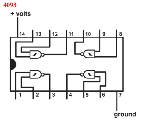
The CD4093B is a CMOS Quad 2-Input NAND Schmitt Trigger integrated circuit, housed in a 14-pin Dual In-line Package (DIP). Manufactured by Texas Instruments, this component is designed to provide enhanced noise immunity and stability in digital circuits through the use of hysteresis. It is commonly utilized in applications such as oscillators, pulse shaping, and signal conditioning.
Explore Projects Built with 4093


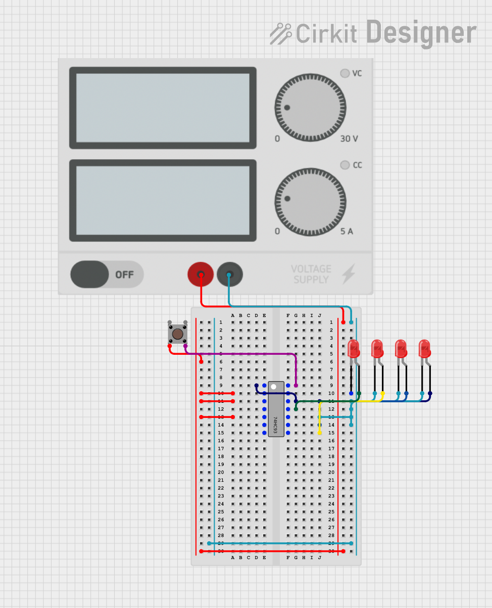
Explore Projects Built with 4093
Common Applications
- Waveform generation
- Signal debouncing
- Logic level conversion
- Timing circuits
- Complex logic functions
Technical Specifications
Absolute Maximum Ratings
| Parameter | Value |
|---|---|
| Supply Voltage (VDD) | -0.5V to +18V |
| Input Voltage (VI) | -0.5V to VDD+0.5V |
| Storage Temperature Range (Tstg) | -65°C to +150°C |
Note: Stresses beyond those listed under "Absolute Maximum Ratings" may cause permanent damage to the device.
Recommended Operating Conditions
| Parameter | Min | Typ | Max | Unit |
|---|---|---|---|---|
| Supply Voltage (VDD) | 3 | 15 | V | |
| Input Voltage (VI) | 0 | VDD | V | |
| Operating Temperature (TA) | -55 | +125 | °C |
Electrical Characteristics (at V<sub>DD</sub>=10V, T<sub>A</sub>=25°C)
| Parameter | Conditions | Min | Typ | Max | Unit |
|---|---|---|---|---|---|
| High-Level Output Voltage (VOH) | IO=-10μA | 9.95 | V | ||
| Low-Level Output Voltage (VOL) | IO=10μA | 0.05 | V | ||
| Input Current (II) | VI=VDD or VSS | ±1 | μA | ||
| Hysteresis Voltage (VH) | 0.4 | 1.0 | 1.6 | V |
Pin Configuration and Descriptions
| Pin Number | Name | Description |
|---|---|---|
| 1 | 1Y | Output of Gate 1 |
| 2 | 1A | Input A of Gate 1 |
| 3 | 1B | Input B of Gate 1 |
| 4 | 2Y | Output of Gate 2 |
| 5 | 2A | Input A of Gate 2 |
| 6 | 2B | Input B of Gate 2 |
| 7 | GND | Ground (0V) |
| 8 | 3A | Input A of Gate 3 |
| 9 | 3B | Input B of Gate 3 |
| 10 | 3Y | Output of Gate 3 |
| 11 | 4A | Input A of Gate 4 |
| 12 | 4B | Input B of Gate 4 |
| 13 | 4Y | Output of Gate 4 |
| 14 | VDD | Positive Supply Voltage |
Usage Instructions
Basic Connection
To use the CD4093B in a circuit:
- Connect VDD (pin 14) to the positive supply voltage (3V to 15V).
- Connect GND (pin 7) to the ground of the circuit.
- Apply input signals to the input pins (1A, 1B, 2A, 2B, etc.).
- The corresponding output pins (1Y, 2Y, etc.) will provide the NAND Schmitt trigger output.
Best Practices
- Ensure that the supply voltage does not exceed the recommended operating voltage range.
- Unused inputs should be tied to VDD or GND to prevent floating inputs which can lead to unpredictable behavior.
- Decoupling capacitors (typically 0.1μF) should be placed close to the VDD and GND pins to filter out noise.
- Avoid applying voltages to the input pins when the power supply is off, as this can cause current to flow into the device leading to damage.
Example Circuit: Simple Oscillator
// Arduino code for generating a square wave using CD4093B

const int outputPin = 2; // Connect to the output of the NAND gate

void setup() {
  pinMode(outputPin, OUTPUT);
}

void loop() {
  // The oscillator frequency is determined by the RC time constant
  // and the hysteresis of the Schmitt trigger.
  // No external components are needed in this example as the
  // internal pull-up provides the required resistance and the
  // capacitance is provided by the gate input capacitance.
  digitalWrite(outputPin, HIGH);
  delay(500); // High for 500ms
  digitalWrite(outputPin, LOW);
  delay(500); // Low for 500ms
}
Note: This code assumes that the Arduino is driving the gate directly. In practice, you would use the CD4093B to drive the gate.
Troubleshooting and FAQs
Common Issues
- Output not toggling: Check if the inputs are connected correctly and are receiving the correct logic levels. Also, verify that the supply voltage is within the specified range.
- Device heating up: This could be due to overvoltage or excessive current draw. Immediately disconnect the power and check the circuit for any shorts or incorrect connections.
- Unstable output: Ensure that all unused inputs are tied to VDD or GND. Also, check for proper decoupling and that the supply voltage is stable.
FAQs
Q: Can the CD4093B be used with a 5V supply? A: Yes, the CD4093B can operate with a supply voltage as low as 3V.
Q: What is the purpose of the hysteresis in the Schmitt trigger? A: Hysteresis provides noise immunity by creating a difference between the input threshold levels for switching from high to low and low to high, which helps to stabilize the output against small fluctuations in the input signal.
Q: How can I increase the frequency of the oscillator circuit? A: You can decrease the resistance or the capacitance in the RC network to increase the frequency of the oscillator.
Q: Is it necessary to use all four gates in the CD4093B? A: No, it is not necessary to use all gates. However, ensure that the inputs of unused gates are tied to VDD or GND to prevent them from floating.
For further assistance, please refer to the Texas Instruments datasheet for the CD4093B, which provides comprehensive details on the device's operation and application notes.