How to Use HW-482: Examples, Pinouts, and Specs
Introduction
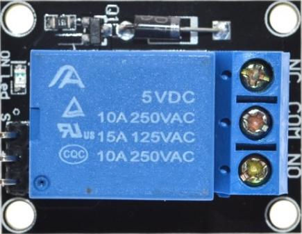
The HW-482 is a versatile electronic component designed for signal processing and control applications. Its compact design makes it ideal for integration into a wide range of devices, from consumer electronics to industrial systems. The HW-482 is known for its reliability, ease of use, and compatibility with various microcontrollers and circuits.
Explore Projects Built with HW-482
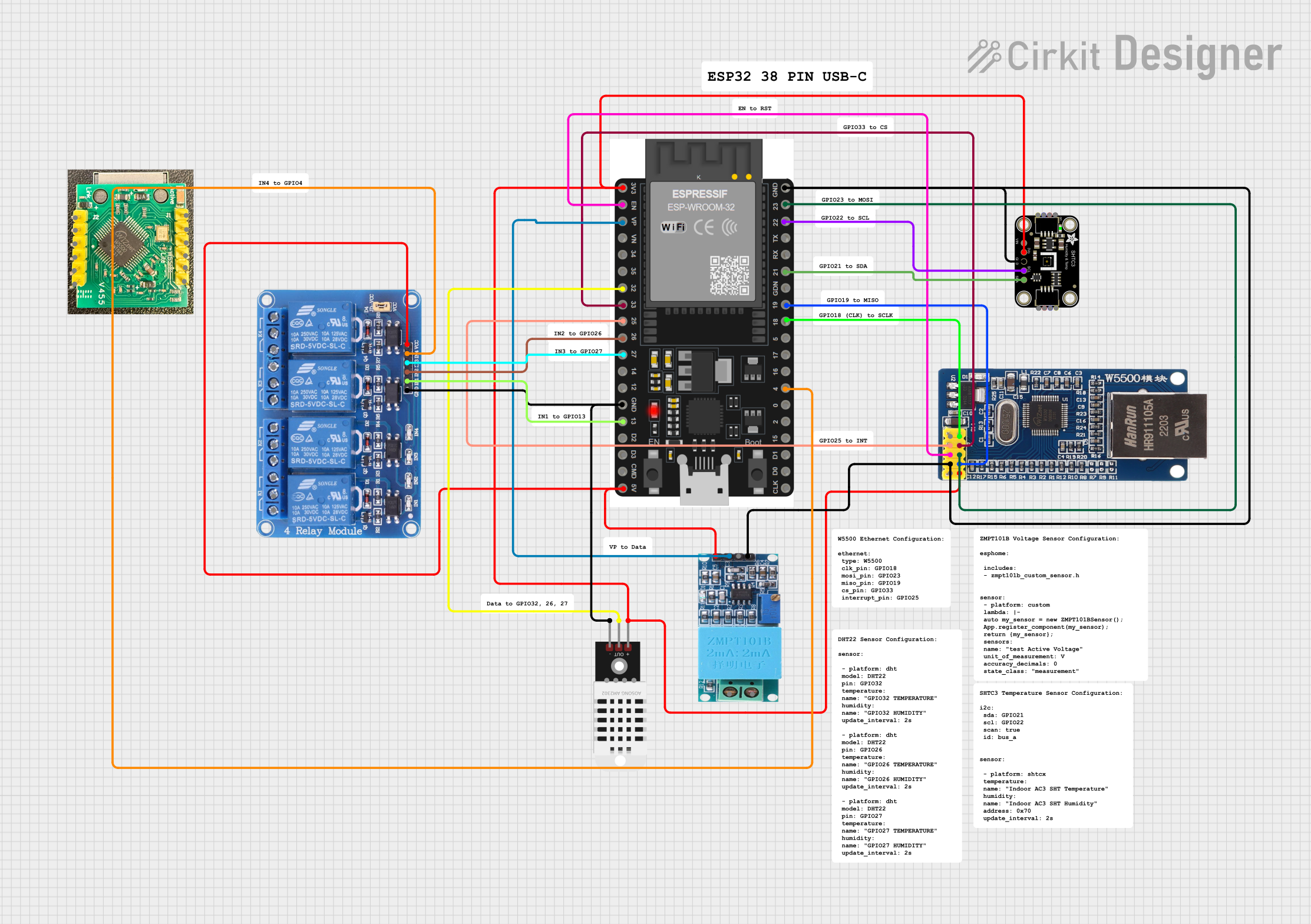
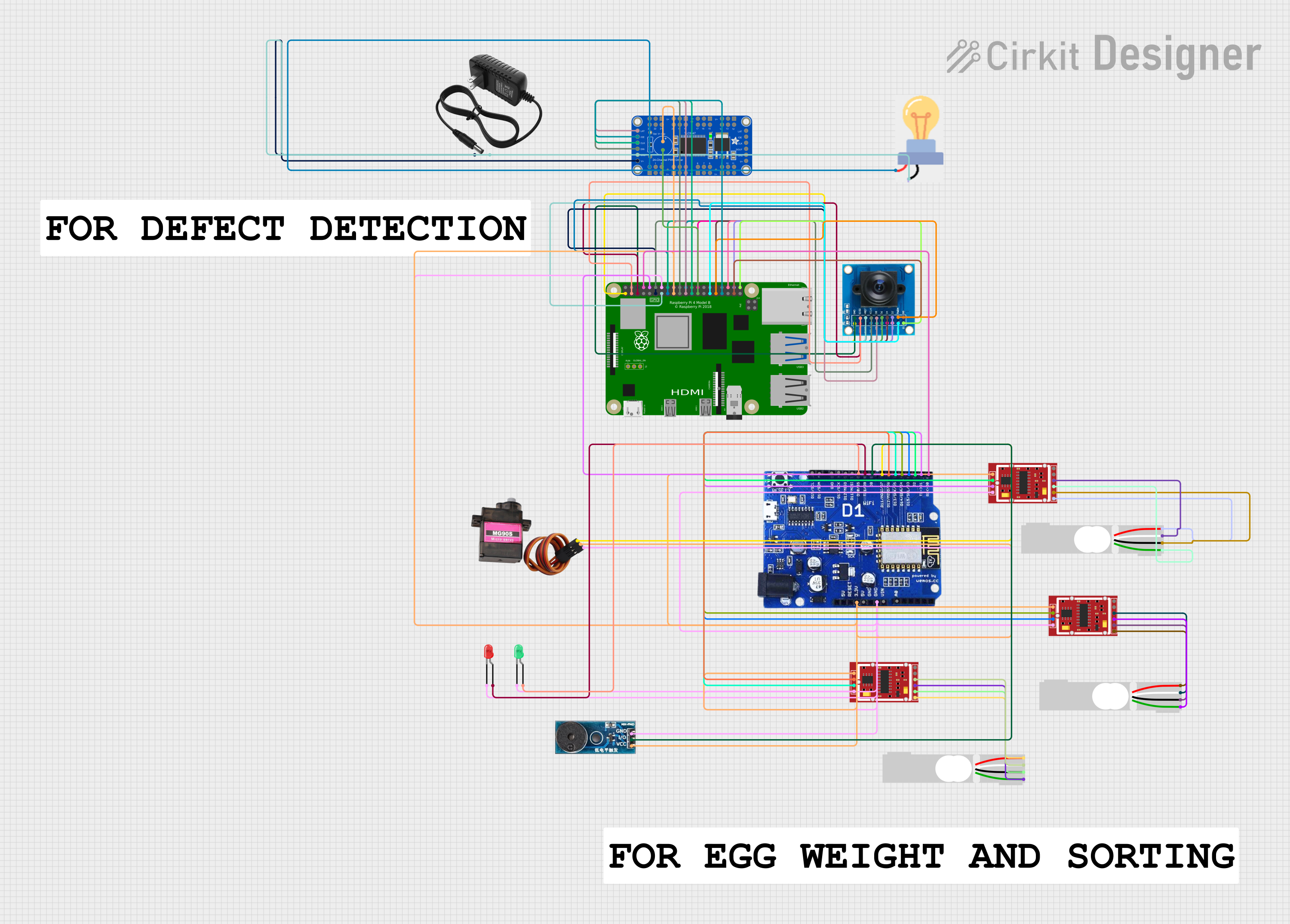
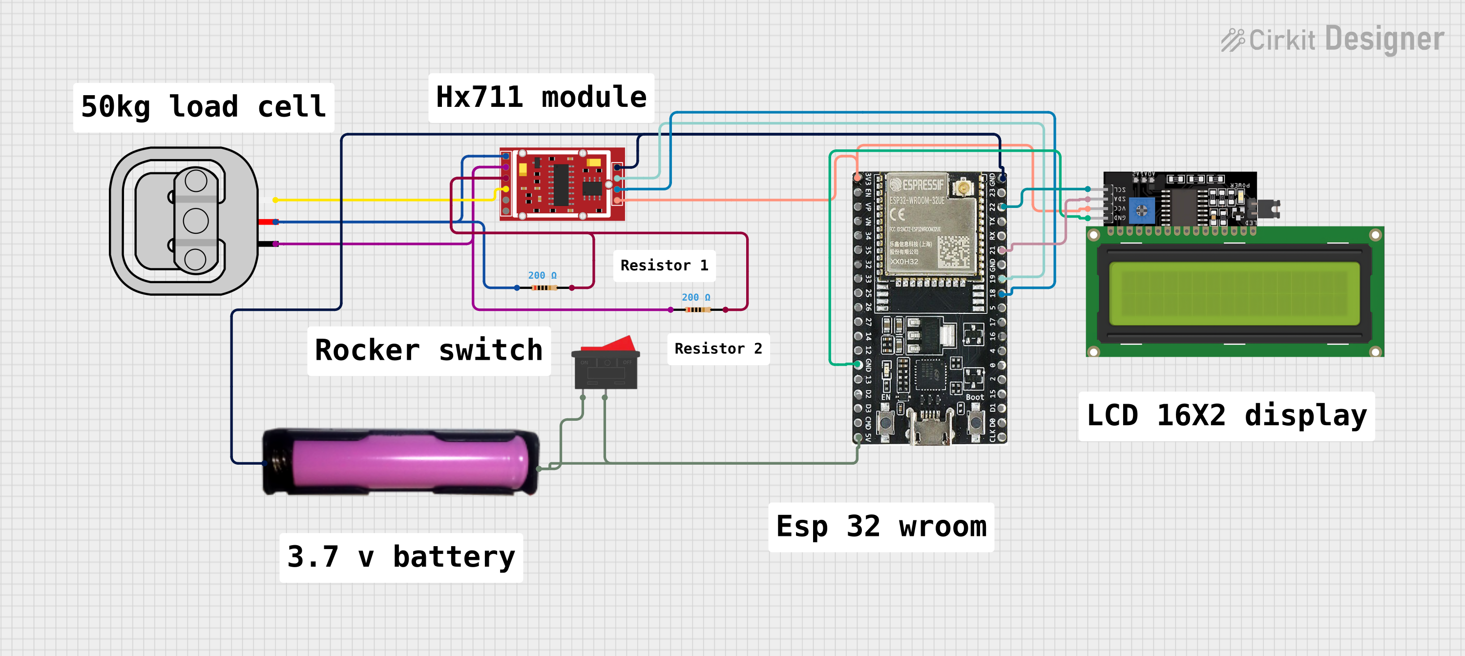

Explore Projects Built with HW-482
Common Applications and Use Cases
- Signal amplification and conditioning
- Motor control systems
- Sensor data processing
- Audio signal processing
- Industrial automation and control systems
Technical Specifications
The HW-482 is designed to operate efficiently in a variety of environments. Below are its key technical specifications:
General Specifications
| Parameter | Value |
|---|---|
| Operating Voltage | 3.3V to 5V |
| Maximum Current | 50mA |
| Signal Frequency Range | 20Hz to 20kHz |
| Operating Temperature | -20°C to 85°C |
| Dimensions | 25mm x 15mm x 5mm |
Pin Configuration and Descriptions
The HW-482 has a 6-pin configuration, as detailed in the table below:
| Pin Number | Pin Name | Description |
|---|---|---|
| 1 | VCC | Power supply input (3.3V to 5V) |
| 2 | GND | Ground connection |
| 3 | IN | Signal input pin |
| 4 | OUT | Signal output pin |
| 5 | ENABLE | Enable/disable control pin (active HIGH) |
| 6 | NC | Not connected (reserved for future use) |
Usage Instructions
The HW-482 is straightforward to use in a variety of circuits. Below are the steps and considerations for integrating it into your project:
How to Use the HW-482 in a Circuit
- Power Supply: Connect the VCC pin to a 3.3V or 5V power source and the GND pin to the ground of your circuit.
- Signal Input: Feed the input signal to the IN pin. Ensure the signal voltage does not exceed the operating voltage range.
- Signal Output: The processed signal will be available at the OUT pin. Connect this pin to the next stage of your circuit.
- Enable Pin: To activate the HW-482, set the ENABLE pin HIGH. If this pin is LOW, the component will be disabled.
- Unused Pins: Leave the NC pin unconnected.
Important Considerations and Best Practices
- Voltage Levels: Ensure the input signal voltage is within the specified range to avoid damage to the component.
- Decoupling Capacitor: Place a 0.1µF decoupling capacitor between VCC and GND to reduce noise and improve stability.
- Heat Management: Although the HW-482 is efficient, ensure proper ventilation if used in high-temperature environments.
- Signal Integrity: Use shielded cables for the input and output signals in noisy environments to maintain signal quality.
Example: Connecting HW-482 to an Arduino UNO
The HW-482 can be easily interfaced with an Arduino UNO for signal processing tasks. Below is an example of how to connect and use it:
Circuit Connections
- Connect the HW-482's VCC pin to the Arduino's 5V pin.
- Connect the GND pin to the Arduino's GND.
- Connect the IN pin to an analog signal source (e.g., a sensor).
- Connect the OUT pin to an analog input pin on the Arduino (e.g., A0).
- Connect the ENABLE pin to a digital output pin on the Arduino (e.g., D7).
Arduino Code Example
// Example code to use HW-482 with Arduino UNO
const int enablePin = 7;  // Pin connected to HW-482 ENABLE pin
const int inputPin = A0;  // Pin connected to HW-482 OUT pin

void setup() {
  pinMode(enablePin, OUTPUT);  // Set ENABLE pin as output
  digitalWrite(enablePin, HIGH);  // Enable the HW-482
  Serial.begin(9600);  // Initialize serial communication
}

void loop() {
  int signalValue = analogRead(inputPin);  // Read signal from HW-482
  Serial.println(signalValue);  // Print the signal value to the Serial Monitor
  delay(100);  // Delay for stability
}
Troubleshooting and FAQs
Common Issues and Solutions
No Output Signal
- Cause: The ENABLE pin is not set HIGH.
- Solution: Ensure the ENABLE pin is connected to a HIGH signal (3.3V or 5V).
Distorted Output Signal
- Cause: Input signal voltage exceeds the operating range.
- Solution: Verify the input signal voltage and ensure it is within the specified range.
Component Overheating
- Cause: Excessive current draw or poor ventilation.
- Solution: Check the circuit for short circuits and ensure proper ventilation.
Noise in Output Signal
- Cause: Power supply noise or interference.
- Solution: Add a decoupling capacitor between VCC and GND and use shielded cables.
FAQs
Q1: Can the HW-482 operate at 12V?
A1: No, the HW-482 is designed to operate within a voltage range of 3.3V to 5V. Using a higher voltage may damage the component.
Q2: Is the HW-482 compatible with 3.3V microcontrollers?
A2: Yes, the HW-482 is fully compatible with 3.3V systems.
Q3: What is the purpose of the NC pin?
A3: The NC (Not Connected) pin is reserved for future use and should be left unconnected in your circuit.
Q4: Can the HW-482 process digital signals?
A4: The HW-482 is primarily designed for analog signal processing. For digital signals, additional circuitry may be required.
This concludes the documentation for the HW-482. For further assistance, refer to the manufacturer's datasheet or contact technical support.