How to Use wireless power reciever coil: Examples, Pinouts, and Specs
Introduction
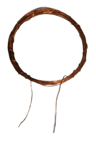
The Wireless Power Receiver Coil (Manufacturer: DIY, Part ID: Receiver Coil 15 Turns) is a key component in inductive charging systems. It is designed to receive energy wirelessly from a transmitter coil by converting the electromagnetic field into electrical energy. This energy can then be used to power electronic devices or charge batteries.
Wireless power receiver coils are commonly used in applications such as:
- Wireless charging pads for smartphones, smartwatches, and other portable devices
- Electric vehicle (EV) wireless charging systems
- Medical devices requiring contactless power transfer
- Industrial automation systems where wired connections are impractical
Explore Projects Built with wireless power reciever coil


Explore Projects Built with wireless power reciever coil
Technical Specifications
Below are the key technical details for the Wireless Power Receiver Coil:
| Parameter | Value |
|---|---|
| Manufacturer | DIY |
| Part ID | Receiver Coil 15 Turns |
| Coil Turns | 15 |
| Inductance | 10 µH (typical) |
| Operating Frequency | 100 kHz – 200 kHz |
| Maximum Input Power | 5 W |
| Output Voltage | 5 V (typical, depends on rectifier circuit) |
| Efficiency | Up to 85% (depending on alignment) |
| Dimensions | 50 mm diameter |
| Wire Material | Copper (enameled) |
| Insulation | Polyurethane coating |
Pin Configuration and Descriptions
The receiver coil itself does not have traditional "pins" but typically connects to a rectifier circuit via two terminals. Below is a description of the terminals:
| Terminal | Description |
|---|---|
| Terminal 1 | Coil input/output terminal (connects to rectifier) |
| Terminal 2 | Coil input/output terminal (connects to rectifier) |
Note: Polarity is not a concern for the coil itself, but proper connection to the rectifier circuit is essential for correct operation.
Usage Instructions
How to Use the Wireless Power Receiver Coil in a Circuit
Connect the Coil to a Rectifier Circuit:
The receiver coil generates an AC voltage when placed in the electromagnetic field of a transmitter coil. This AC voltage must be rectified and regulated to provide a stable DC output. Use a bridge rectifier and a voltage regulator circuit for this purpose.Align the Receiver and Transmitter Coils:
For optimal power transfer, ensure that the receiver coil is aligned with the transmitter coil. Misalignment can significantly reduce efficiency.Test the System:
Place the receiver coil within the operating range of the transmitter coil. Measure the output voltage and current to ensure they meet the requirements of your application.
Important Considerations and Best Practices
- Operating Frequency: Ensure the transmitter coil operates within the specified frequency range (100 kHz – 200 kHz) for compatibility.
- Distance and Alignment: The efficiency of power transfer decreases with distance and misalignment. Keep the coils as close and aligned as possible.
- Heat Management: Prolonged operation at high power levels may cause the coil to heat up. Ensure proper ventilation or cooling if necessary.
- Load Matching: Use a load that matches the power output of the receiver coil to maximize efficiency.
Example: Using the Receiver Coil with an Arduino UNO
To demonstrate the use of the receiver coil, you can connect it to an Arduino UNO to monitor the voltage output. Below is an example code snippet:
// Example code to monitor the voltage output of a wireless power receiver coil
// using an Arduino UNO. The voltage is read via an analog pin and displayed
// on the Serial Monitor.

const int voltagePin = A0; // Analog pin connected to the rectified output
float voltage = 0.0;       // Variable to store the measured voltage

void setup() {
  Serial.begin(9600); // Initialize serial communication at 9600 baud
  pinMode(voltagePin, INPUT); // Set the voltage pin as input
}

void loop() {
  int sensorValue = analogRead(voltagePin); // Read the analog value
  voltage = sensorValue * (5.0 / 1023.0);   // Convert to voltage (5V reference)

  // Print the voltage to the Serial Monitor
  Serial.print("Voltage: ");
  Serial.print(voltage);
  Serial.println(" V");

  delay(1000); // Wait for 1 second before the next reading
}
Note: Ensure the rectified output voltage does not exceed the Arduino's input voltage range (0–5 V).
Troubleshooting and FAQs
Common Issues and Solutions
No Output Voltage:
- Cause: The receiver coil is not within the range of the transmitter coil.
- Solution: Ensure proper alignment and reduce the distance between the coils.
Low Efficiency:
- Cause: Misalignment or interference from nearby metal objects.
- Solution: Align the coils carefully and remove any metallic objects near the system.
Overheating:
- Cause: Prolonged operation at high power levels or poor ventilation.
- Solution: Improve cooling or reduce the power level.
Fluctuating Output Voltage:
- Cause: Instability in the transmitter's power supply or poor coupling.
- Solution: Check the transmitter's power supply and ensure proper alignment.
FAQs
Q1: Can this receiver coil be used with any transmitter coil?
A1: The receiver coil is compatible with transmitter coils operating within the 100 kHz – 200 kHz frequency range. Ensure the transmitter's power output matches the receiver's specifications.
Q2: What is the maximum distance between the transmitter and receiver coils?
A2: The effective range depends on the transmitter's power and coil design but is typically a few millimeters to a few centimeters.
Q3: Can this coil be used for high-power applications?
A3: This coil is designed for low-power applications (up to 5 W). For higher power, consider using a coil with a higher power rating.
Q4: Does the coil require additional components to function?
A4: Yes, the coil requires a rectifier and voltage regulator circuit to convert the AC output into a usable DC voltage.
By following this documentation, you can effectively integrate the Wireless Power Receiver Coil into your projects and troubleshoot common issues.