How to Use Kitronic Autonomous Robotic Platform - Line Follower Board: Examples, Pinouts, and Specs
Introduction
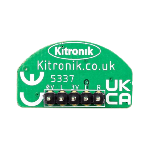
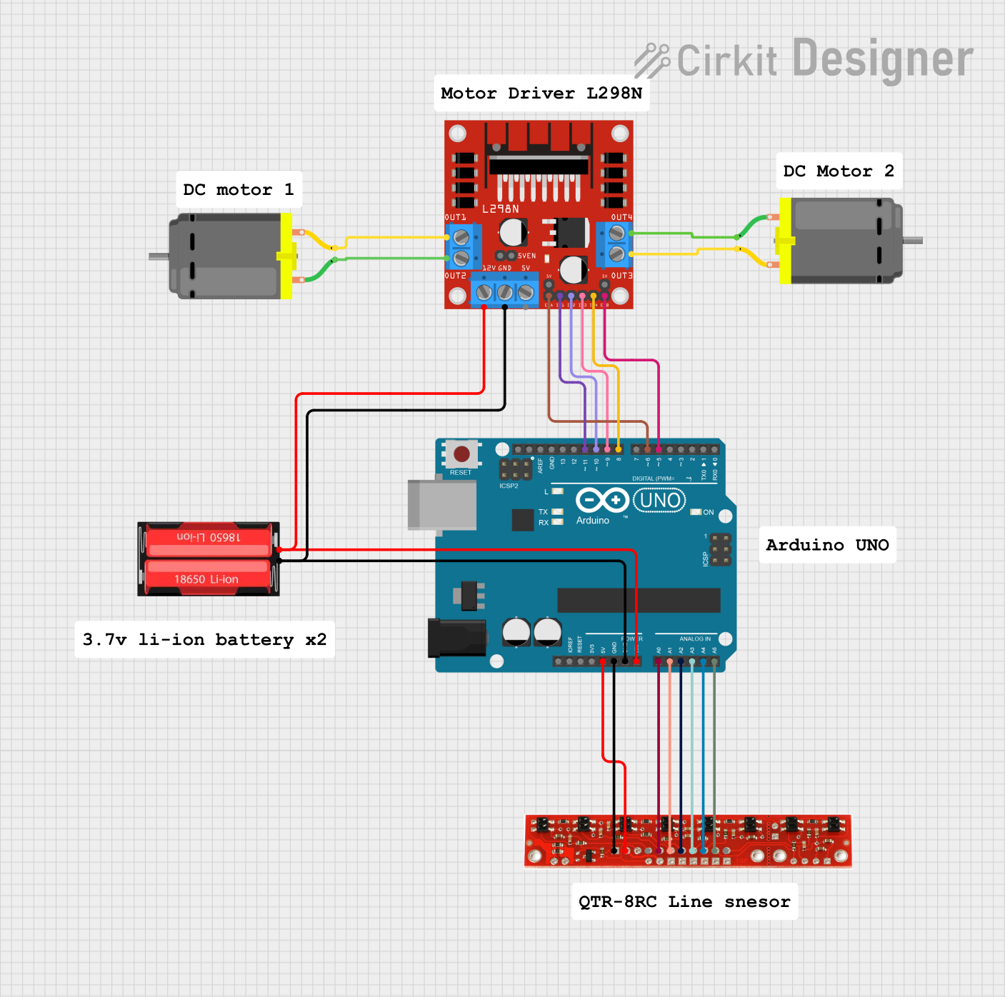
The Kitronic Line Follower Board is a specialized circuit board designed to enhance the functionality of the Kitronic Autonomous Robotic Platform. This board enables the robot to detect and follow lines on the ground using infrared (IR) sensors. It is an essential component for robotics projects that require autonomous navigation along predefined paths.
Explore Projects Built with Kitronic Autonomous Robotic Platform - Line Follower Board
Explore Projects Built with Kitronic Autonomous Robotic Platform - Line Follower Board
Common Applications and Use Cases
- Autonomous robotic navigation
- Line-following competitions
- Educational robotics projects
- Industrial automation systems
- Prototyping for autonomous vehicles
Technical Specifications
The Line Follower Board is equipped with multiple IR sensors and is designed to interface seamlessly with the Kitronic Autonomous Robotic Platform. Below are the key technical details:
General Specifications
| Parameter | Value |
|---|---|
| Manufacturer | Kitronic |
| Part ID | Line Follower Board |
| Operating Voltage | 3.3V to 5V |
| Current Consumption | ~20mA (typical) |
| Number of IR Sensors | 5 |
| Output Type | Digital (High/Low) |
| Dimensions | 70mm x 30mm x 10mm |
| Mounting Compatibility | Kitronic Autonomous Platform |
Pin Configuration and Descriptions
| Pin Name | Pin Type | Description |
|---|---|---|
| VCC | Power | Connect to a 3.3V or 5V power supply. |
| GND | Ground | Connect to the ground of the power supply. |
| OUT1 | Digital I/O | Output signal from the first IR sensor (leftmost sensor). |
| OUT2 | Digital I/O | Output signal from the second IR sensor. |
| OUT3 | Digital I/O | Output signal from the center IR sensor. |
| OUT4 | Digital I/O | Output signal from the fourth IR sensor. |
| OUT5 | Digital I/O | Output signal from the fifth IR sensor (rightmost sensor). |
Usage Instructions
How to Use the Line Follower Board in a Circuit
- Power Connection: Connect the
VCCpin to a 3.3V or 5V power source and theGNDpin to the ground. - Sensor Outputs: Connect the
OUT1toOUT5pins to the corresponding digital input pins of your microcontroller or robotic platform. - Mounting: Secure the Line Follower Board to the Kitronic Autonomous Robotic Platform using the provided mounting points.
- Calibration: Place the robot on a surface with a clear line (e.g., black line on a white background). Adjust the sensitivity of the IR sensors if required (refer to the Kitronic platform manual for details).
Important Considerations and Best Practices
- Ensure the board is mounted at an appropriate height above the surface (typically 5-10mm) for optimal sensor performance.
- Use a clean, high-contrast line for best results (e.g., black electrical tape on a white surface).
- Avoid using the board in environments with excessive ambient IR light, as it may interfere with sensor readings.
- Regularly clean the IR sensors to remove dust or debris that could affect performance.
Example Code for Arduino UNO
Below is an example code snippet to interface the Line Follower Board with an Arduino UNO:
// Define the pins connected to the Line Follower Board
#define SENSOR1_PIN 2  // Leftmost sensor
#define SENSOR2_PIN 3  // Second sensor
#define SENSOR3_PIN 4  // Center sensor
#define SENSOR4_PIN 5  // Fourth sensor
#define SENSOR5_PIN 6  // Rightmost sensor

void setup() {
  // Initialize serial communication for debugging
  Serial.begin(9600);

  // Set sensor pins as inputs
  pinMode(SENSOR1_PIN, INPUT);
  pinMode(SENSOR2_PIN, INPUT);
  pinMode(SENSOR3_PIN, INPUT);
  pinMode(SENSOR4_PIN, INPUT);
  pinMode(SENSOR5_PIN, INPUT);
}

void loop() {
  // Read the state of each sensor
  int sensor1 = digitalRead(SENSOR1_PIN);
  int sensor2 = digitalRead(SENSOR2_PIN);
  int sensor3 = digitalRead(SENSOR3_PIN);
  int sensor4 = digitalRead(SENSOR4_PIN);
  int sensor5 = digitalRead(SENSOR5_PIN);

  // Print sensor states to the Serial Monitor
  Serial.print("S1: "); Serial.print(sensor1);
  Serial.print(" S2: "); Serial.print(sensor2);
  Serial.print(" S3: "); Serial.print(sensor3);
  Serial.print(" S4: "); Serial.print(sensor4);
  Serial.print(" S5: "); Serial.println(sensor5);

  // Add your line-following logic here
  delay(100);  // Small delay for stability
}
Troubleshooting and FAQs
Common Issues and Solutions
Sensors Not Detecting the Line:
- Ensure the board is powered correctly (check
VCCandGNDconnections). - Verify that the line is of sufficient contrast (e.g., black on white).
- Clean the IR sensors to remove any dust or debris.
- Ensure the board is powered correctly (check
Erratic Sensor Readings:
- Check for ambient IR interference (e.g., sunlight or IR-emitting devices).
- Adjust the height of the board above the surface for optimal detection.
No Output from Sensors:
- Confirm that the output pins are connected to the correct microcontroller pins.
- Test the board with a multimeter to ensure it is functioning properly.
FAQs
Q: Can the Line Follower Board be used with other robotic platforms?
A: Yes, the board can be used with other platforms, provided the power and pin configurations are compatible.
Q: How do I adjust the sensitivity of the sensors?
A: The sensitivity can typically be adjusted using onboard potentiometers or through software calibration, depending on the platform.
Q: What is the optimal surface for line-following?
A: A flat, clean surface with a high-contrast line (e.g., black electrical tape on a white background) is ideal.
Q: Can the board detect curved lines?
A: Yes, the board can detect curved lines as long as the curve radius is not too tight for the robot to follow.