How to Use LM317 Voltage Regulator: Examples, Pinouts, and Specs
Introduction
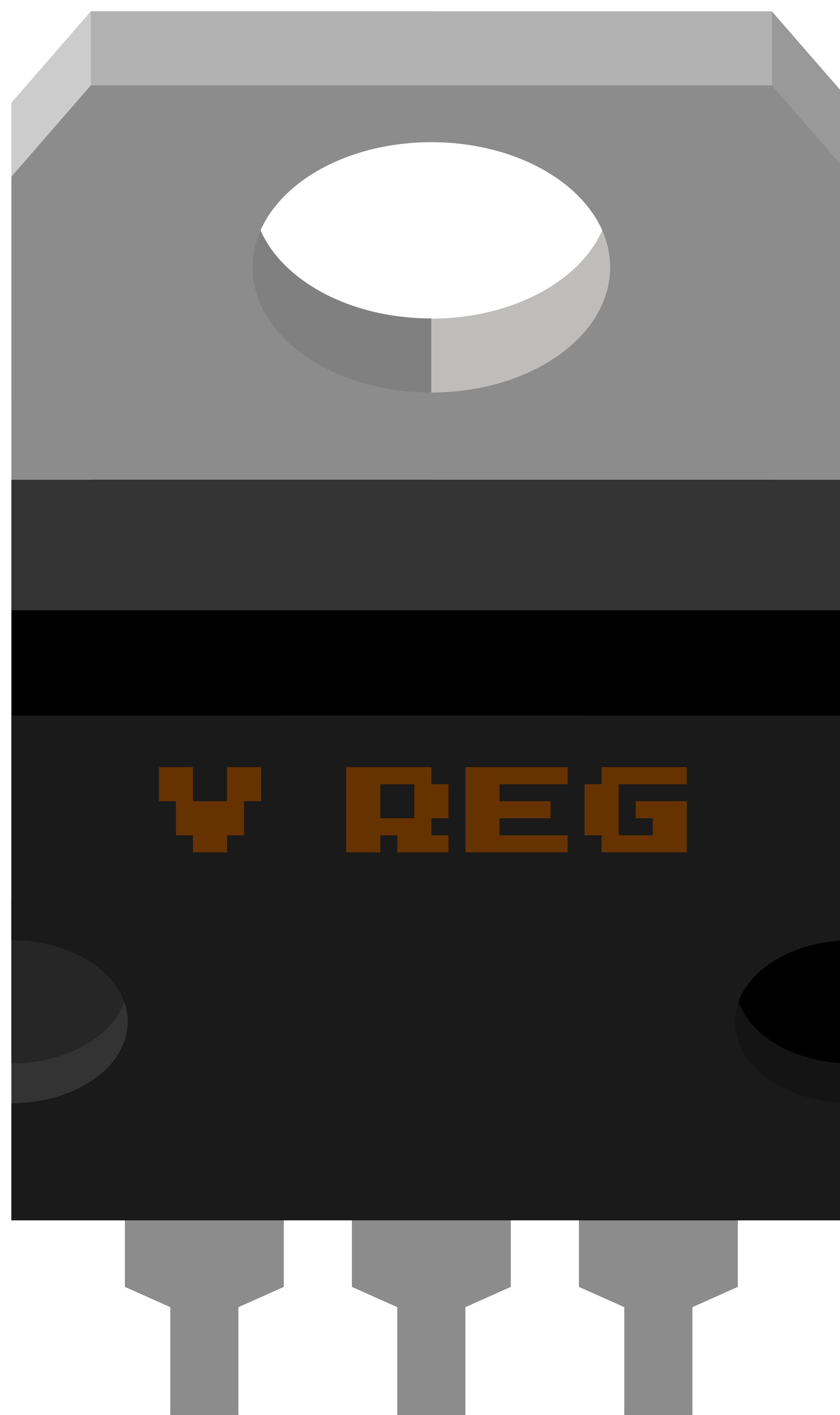
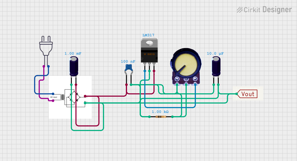
The LM317 is a popular adjustable three-terminal positive voltage regulator, designed to supply more than 1.5A of output current with an adjustable output voltage from 1.25V to 37V. This component is widely used in power supply circuits where a variable voltage is required. It is especially useful for custom electronics projects, battery chargers, and as a part of a larger power management system.
Explore Projects Built with LM317 Voltage Regulator
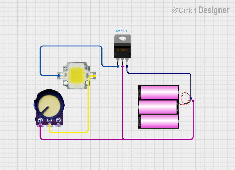
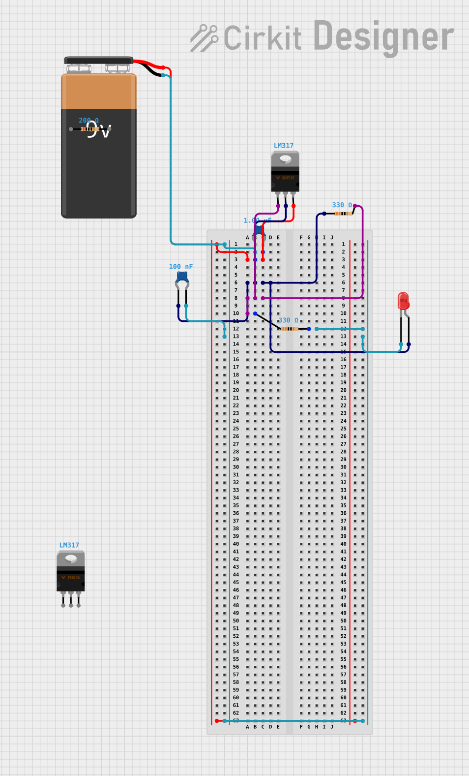
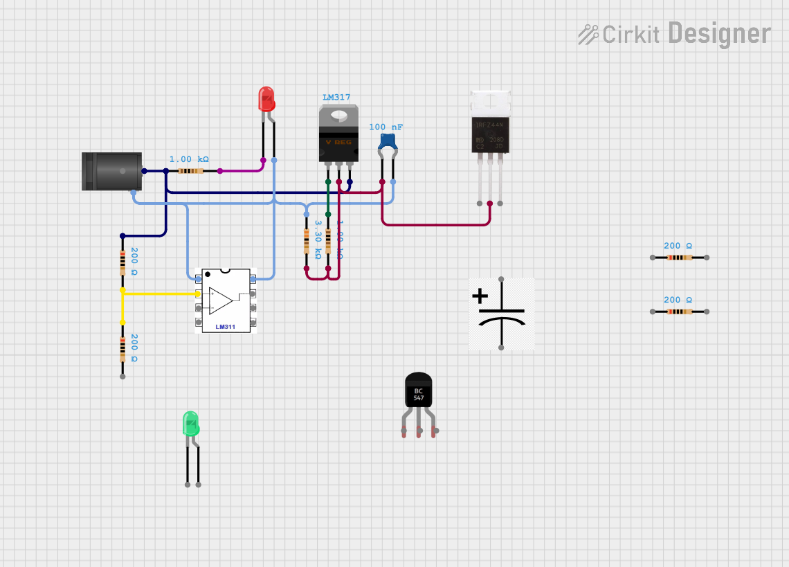
Explore Projects Built with LM317 Voltage Regulator
Common Applications and Use Cases
- Adjustable power supplies
- Battery chargers
- Motor control systems
- LED drivers
- Benchtop lab power supplies
Technical Specifications
Key Technical Details
- Output Voltage Range: 1.25V to 37V
- Output Current: 1.5A (max)
- Input-Output Differential (V_I - V_O): 3V (min)
- Line Regulation: Typically 0.01% / V
- Load Regulation: Typically 0.1%
- Operating Temperature Range: 0°C to 125°C
Pin Configuration and Descriptions
| Pin Number | Name | Description |
|---|---|---|
| 1 | ADJ | Adjust pin, used to set the output voltage |
| 2 | OUT | Regulated output voltage |
| 3 | IN | Input voltage (must be higher than the desired output voltage) |
Usage Instructions
How to Use the LM317 in a Circuit
- Connect the input voltage to the IN pin. Ensure that the input voltage is at least 3V greater than the desired output voltage.
- Connect the output load to the OUT pin.
- Use a resistor (R1) between the OUT pin and the ADJ pin. A typical value for R1 is 240 ohms.
- Connect a second resistor (R2) from the ADJ pin to ground. The value of R2 will determine the output voltage.
- The output voltage can be calculated using the formula: V_OUT = 1.25V * (1 + R2/R1) + (I_ADJ * R2)
- Add capacitors to the input and output for stability. A typical value is 0.1µF for the input and 1µF for the output.
Important Considerations and Best Practices
- Ensure that the input voltage always remains at least 3V above the output voltage to maintain regulation.
- The maximum output current is 1.5A, but this is dependent on the heat sinking provided. Without adequate heat sinking, the regulator may overheat.
- The ADJ pin current (I_ADJ) is typically 50µA and should be taken into account for precise voltage regulation.
- Use capacitors on the input and output to minimize ripple and noise.
- Avoid running the LM317 at its maximum ratings for extended periods to ensure reliability.
Troubleshooting and FAQs
Common Issues
- Output voltage is too low or too high: Check the values of R1 and R2, and ensure they are correctly calculated for the desired output voltage.
- Regulator is overheating: Ensure that the input voltage is not too high and that the regulator has adequate heat sinking.
- Output voltage is unstable: Verify that the capacitors are correctly placed and are of the recommended values.
Solutions and Tips for Troubleshooting
- Double-check the connections and ensure that the polarity is correct.
- Measure the input voltage to ensure it is sufficient.
- Use a multimeter to verify the resistance values of R1 and R2.
- Ensure that the capacitors are not damaged and are properly soldered.
FAQs
Q: Can I use the LM317 to regulate current as well as voltage? A: Yes, the LM317 can be used in a constant current configuration by placing a resistor from the output to the ADJ pin and connecting the load in series with the output.
Q: What is the maximum input voltage for the LM317? A: The maximum input voltage is typically 40V, but you should always check the datasheet for the specific part you are using.
Q: How can I improve the output voltage precision? A: Use precision resistors for R1 and R2, and consider the temperature coefficient. Also, account for the ADJ pin current in your calculations.
Example Code for Arduino UNO
Below is an example code snippet for using the LM317 with an Arduino UNO to read the output voltage through an analog pin. This assumes you have a voltage divider or a method to safely bring the voltage within the Arduino's input range (0-5V).
const int analogPin = A0; // Analog pin for voltage reading

void setup() {
  Serial.begin(9600);
}

void loop() {
  int sensorValue = analogRead(analogPin); // Read the analog input
  float voltage = sensorValue * (5.0 / 1023.0); // Convert to voltage
  Serial.print("Output Voltage: ");
  Serial.println(voltage);
  delay(1000); // Wait for a second
}
Note: This code is for demonstration purposes only. Ensure that the output voltage of the LM317 is within the safe range for the Arduino analog input. If necessary, use a voltage divider to step down the voltage.