
How to Use Adafruit ADXL377: Examples, Pinouts, and Specs
 Design with Adafruit ADXL377 in Cirkit Designer
Introduction
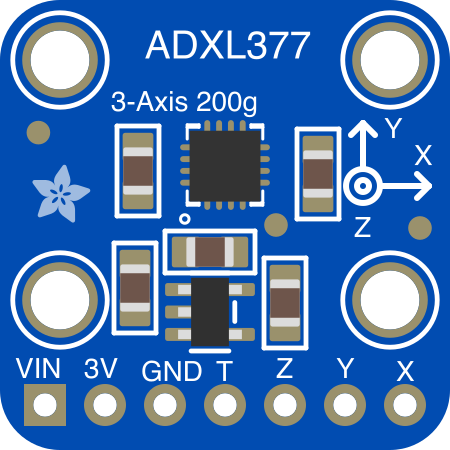
The Adafruit ADXL377 (Manufacturer Part ID: 1413) is a high-performance, low-power accelerometer designed to measure acceleration in three axes (X, Y, and Z). It is capable of measuring high-g forces up to ±200g, making it ideal for applications requiring precise motion sensing in extreme conditions. This component is widely used in sports equipment, industrial monitoring, robotics, and impact detection systems.
Explore Projects Built with Adafruit ADXL377
 Open Project in Cirkit Designer
 Open Project in Cirkit Designer
 Open Project in Cirkit Designer
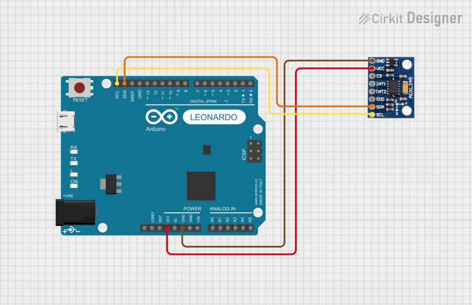 Open Project in Cirkit Designer
Explore Projects Built with Adafruit ADXL377
Open Project in Cirkit DesignerOpen Project in Cirkit DesignerOpen Project in Cirkit DesignerOpen Project in Cirkit DesignerCommon Applications:
- High-impact sports equipment (e.g., helmets, protective gear)
- Robotics and drone navigation
- Industrial vibration and shock monitoring
- Automotive crash testing
- Motion tracking and logging systems
Technical Specifications
The Adafruit ADXL377 is built for high-performance motion sensing with the following key specifications:
| Parameter | Value |
|---|---|
| Supply Voltage (Vcc) | 3.3V to 5V |
| Measurement Range | ±200g |
| Sensitivity | 6.5 mV/g |
| Bandwidth | Up to 1600 Hz |
| Operating Temperature | -40°C to +85°C |
| Power Consumption | 0.3 mA (typical) |
| Output Type | Analog |
| Dimensions | 20mm x 20mm x 3mm |
Pin Configuration and Descriptions
The ADXL377 breakout board has six pins, as described in the table below:
| Pin | Name | Description |
|---|---|---|
| 1 | VCC | Power supply input (3.3V to 5V). Connect to the power source of your circuit. |
| 2 | GND | Ground. Connect to the ground of your circuit. |
| 3 | XOUT | Analog output for acceleration along the X-axis. |
| 4 | YOUT | Analog output for acceleration along the Y-axis. |
| 5 | ZOUT | Analog output for acceleration along the Z-axis. |
| 6 | ST | Self-test pin. Leave unconnected for normal operation. |
Usage Instructions
Connecting the ADXL377 to a Circuit
- Power Supply: Connect the
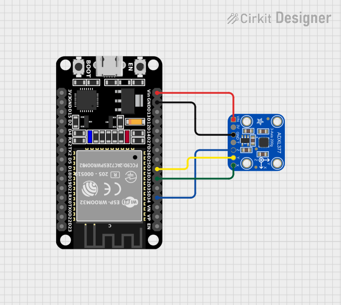
VCCpin to a 3.3V or 5V power source and theGNDpin to the ground of your circuit. - Signal Outputs: Connect the
XOUT,YOUT, andZOUTpins to the analog input pins of your microcontroller or data acquisition system. - Self-Test (Optional): The
STpin can be used to verify the functionality of the accelerometer. Leave it unconnected for normal operation.
Important Considerations:
- Voltage Levels: Ensure the power supply voltage matches the operating range of the ADXL377 (3.3V to 5V).
- Filtering: Use external capacitors on the output pins to limit noise and adjust the bandwidth. For example, a 0.1 µF capacitor can be used to set the bandwidth to approximately 50 Hz.
- Orientation: Mount the sensor securely to ensure accurate readings and minimize vibrations.
- Analog-to-Digital Conversion: If using a microcontroller, ensure its ADC resolution is sufficient to capture the small voltage changes from the sensor.
Example: Using ADXL377 with Arduino UNO
Below is an example of how to read acceleration data from the ADXL377 using an Arduino UNO:
// Define the analog input pins for the ADXL377
const int xPin = A0; // X-axis output connected to A0
const int yPin = A1; // Y-axis output connected to A1
const int zPin = A2; // Z-axis output connected to A2

// Sensitivity of the ADXL377 in mV/g
const float sensitivity = 6.5; // 6.5 mV per g

// Reference voltage of the Arduino (typically 5V or 3.3V)
const float vRef = 5.0;

void setup() {
  Serial.begin(9600); // Initialize serial communication
}

void loop() {
  // Read raw analog values from the ADXL377
  int xRaw = analogRead(xPin);
  int yRaw = analogRead(yPin);
  int zRaw = analogRead(zPin);

  // Convert raw values to voltage
  float xVoltage = (xRaw / 1023.0) * vRef;
  float yVoltage = (yRaw / 1023.0) * vRef;
  float zVoltage = (zRaw / 1023.0) * vRef;

  // Calculate acceleration in g
  float xAccel = (xVoltage - (vRef / 2)) / (sensitivity / 1000);
  float yAccel = (yVoltage - (vRef / 2)) / (sensitivity / 1000);
  float zAccel = (zVoltage - (vRef / 2)) / (sensitivity / 1000);

  // Print acceleration values to the Serial Monitor
  Serial.print("X: ");
  Serial.print(xAccel);
  Serial.print(" g, Y: ");
  Serial.print(yAccel);
  Serial.print(" g, Z: ");
  Serial.print(zAccel);
  Serial.println(" g");

  delay(100); // Delay for 100ms before the next reading
}
Notes:
- The
sensitivityvalue (6.5 mV/g) is used to convert the voltage readings into acceleration values in g. - The reference voltage (
vRef) should match the voltage supplied to the ADXL377.
Troubleshooting and FAQs
Common Issues:
No Output or Incorrect Readings:
- Cause: Incorrect wiring or loose connections.
- Solution: Double-check all connections, ensuring the
VCCandGNDpins are properly connected.
High Noise in Output:
- Cause: Lack of filtering capacitors or external interference.
- Solution: Add capacitors to the output pins to reduce noise. Use shielded cables if necessary.
Output Saturation:
- Cause: Acceleration exceeds the ±200g range.
- Solution: Ensure the application does not exceed the sensor's measurement range.
Self-Test Not Working:
- Cause: Incorrect use of the
STpin. - Solution: Refer to the ADXL377 datasheet for proper self-test procedures.
- Cause: Incorrect use of the
FAQs:
Q1: Can I use the ADXL377 with a 3.3V microcontroller?
A1: Yes, the ADXL377 operates within a voltage range of 3.3V to 5V, making it compatible with 3.3V microcontrollers.
Q2: How do I adjust the bandwidth of the ADXL377?
A2: The bandwidth can be adjusted by adding external capacitors to the XOUT, YOUT, and ZOUT pins. Refer to the datasheet for recommended capacitor values.
Q3: What is the maximum sampling rate for the ADXL377?
A3: The ADXL377 supports a bandwidth of up to 1600 Hz, which corresponds to a maximum sampling rate of 3200 samples per second.
Q4: Can the ADXL377 detect free fall?
A4: While the ADXL377 is designed for high-g applications, it can detect free fall if the acceleration drops to near zero on all axes. However, it is not optimized for low-g applications.
By following this documentation, you can effectively integrate the Adafruit ADXL377 into your projects and achieve accurate motion sensing in high-impact environments.