How to Use Spectra 1738 v2.40: Examples, Pinouts, and Specs
Introduction
The Spectra 1738 v2.40, manufactured by Paradox (Part ID: 1738), is a high-performance signal processing unit designed for audio applications. It features advanced digital signal processing (DSP) capabilities, multiple input/output options, and customizable settings to deliver optimal sound quality. This component is ideal for use in professional audio systems, home theaters, and other sound engineering applications where precision and flexibility are critical.
Explore Projects Built with Spectra 1738 v2.40


Explore Projects Built with Spectra 1738 v2.40
Common Applications and Use Cases
- Professional audio mixing and mastering
- Home theater systems for enhanced sound quality
- Live sound reinforcement and public address systems
- Audio signal conditioning in recording studios
- Customizable audio effects for musical instruments
Technical Specifications
Key Technical Details
| Parameter | Specification |
|---|---|
| Operating Voltage | 5V DC |
| Power Consumption | 1.2W (typical) |
| Input Channels | 2 (stereo) |
| Output Channels | 2 (stereo) |
| Signal-to-Noise Ratio | 110 dB |
| Frequency Response | 20 Hz to 20 kHz |
| Total Harmonic Distortion | < 0.01% |
| DSP Resolution | 24-bit |
| Sampling Rate | 48 kHz |
| Communication Interface | I2C |
| Operating Temperature | -10°C to 60°C |
| Dimensions | 50mm x 30mm x 10mm |
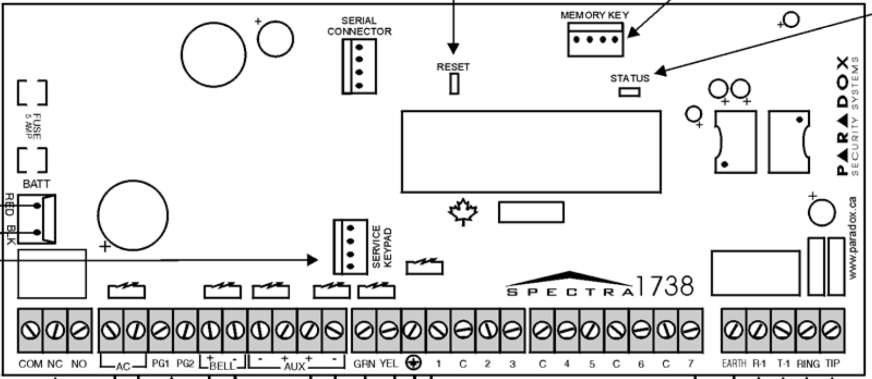
Pin Configuration and Descriptions
| Pin Number | Pin Name | Description |
|---|---|---|
| 1 | VCC | Power supply input (5V DC) |
| 2 | GND | Ground connection |
| 3 | SDA | I2C data line |
| 4 | SCL | I2C clock line |
| 5 | IN_L | Left channel audio input |
| 6 | IN_R | Right channel audio input |
| 7 | OUT_L | Left channel audio output |
| 8 | OUT_R | Right channel audio output |
| 9 | RESET | Active-low reset pin |
| 10 | CONFIG | Configuration pin for custom settings |
Usage Instructions
How to Use the Component in a Circuit
- Power Supply: Connect the VCC pin to a stable 5V DC power source and the GND pin to ground.
- Audio Input: Feed the left and right audio signals into the IN_L and IN_R pins, respectively.
- Audio Output: Connect the OUT_L and OUT_R pins to the desired output device, such as speakers or amplifiers.
- I2C Communication: Use the SDA and SCL pins to interface with a microcontroller or DSP controller for configuration and control.
- Reset: If needed, use the RESET pin to initialize the component to its default state.
- Configuration: Use the CONFIG pin to load custom settings or presets as required.
Important Considerations and Best Practices
- Ensure the power supply is stable and within the specified voltage range to avoid damage.
- Use shielded cables for audio input and output to minimize noise and interference.
- Properly terminate unused input/output pins to prevent signal degradation.
- When interfacing with a microcontroller, ensure the I2C pull-up resistors are correctly configured.
- Avoid exposing the component to temperatures outside the specified operating range.
Example: Connecting to an Arduino UNO
The Spectra 1738 v2.40 can be easily interfaced with an Arduino UNO for configuration and control via the I2C interface. Below is an example code snippet:
#include <Wire.h> // Include the Wire library for I2C communication

#define SPECTRA_ADDR 0x40 // I2C address of the Spectra 1738

void setup() {
  Wire.begin(); // Initialize I2C communication
  Serial.begin(9600); // Initialize serial communication for debugging

  // Reset the Spectra 1738
  pinMode(9, OUTPUT); // Set Arduino pin 9 as output for RESET
  digitalWrite(9, LOW); // Pull RESET pin low
  delay(10); // Wait for 10ms
  digitalWrite(9, HIGH); // Release RESET pin
  delay(100); // Wait for the component to initialize

  // Configure the Spectra 1738
  Wire.beginTransmission(SPECTRA_ADDR);
  Wire.write(0x01); // Example register address
  Wire.write(0x80); // Example configuration value
  Wire.endTransmission();

  Serial.println("Spectra 1738 initialized and configured.");
}

void loop() {
  // Example: Read a status register from the Spectra 1738
  Wire.beginTransmission(SPECTRA_ADDR);
  Wire.write(0x02); // Example status register address
  Wire.endTransmission();

  Wire.requestFrom(SPECTRA_ADDR, 1); // Request 1 byte of data
  if (Wire.available()) {
    byte status = Wire.read();
    Serial.print("Status: ");
    Serial.println(status, HEX);
  }

  delay(1000); // Wait for 1 second before the next read
}
Troubleshooting and FAQs
Common Issues and Solutions
No Output Signal
- Cause: Incorrect wiring or configuration.
- Solution: Verify all connections, especially the audio input/output and power supply. Check the I2C configuration.
Distorted Audio
- Cause: Signal levels are too high or low.
- Solution: Ensure the input signal levels are within the acceptable range. Use appropriate pre-amplification or attenuation if necessary.
I2C Communication Failure
- Cause: Incorrect I2C address or missing pull-up resistors.
- Solution: Double-check the I2C address and ensure pull-up resistors are properly connected.
Component Overheating
- Cause: Excessive power supply voltage or poor ventilation.
- Solution: Ensure the power supply voltage is within the specified range and provide adequate cooling.
FAQs
Q: Can the Spectra 1738 v2.40 process mono audio signals?
A: Yes, you can use either the left or right channel input for mono signals.Q: What is the default I2C address of the Spectra 1738?
A: The default I2C address is0x40.Q: Can I use the Spectra 1738 with a 3.3V microcontroller?
A: Yes, but you will need a level shifter for the I2C lines to ensure compatibility.Q: How do I reset the component to factory settings?
A: Pull the RESET pin low for at least 10ms, then release it.
This documentation provides a comprehensive guide to using the Spectra 1738 v2.40 effectively in your audio projects. For further assistance, refer to the manufacturer's datasheet or contact Paradox support.