How to Use PWM Relay: Examples, Pinouts, and Specs
Introduction
A PWM (Pulse Width Modulation) relay is an electromechanical switch designed to control the power delivered to a load using PWM signals. By varying the duty cycle of the PWM signal, the relay enables precise control over parameters such as speed, brightness, or temperature. This makes it an efficient and versatile component for applications requiring variable power delivery.
Explore Projects Built with PWM Relay
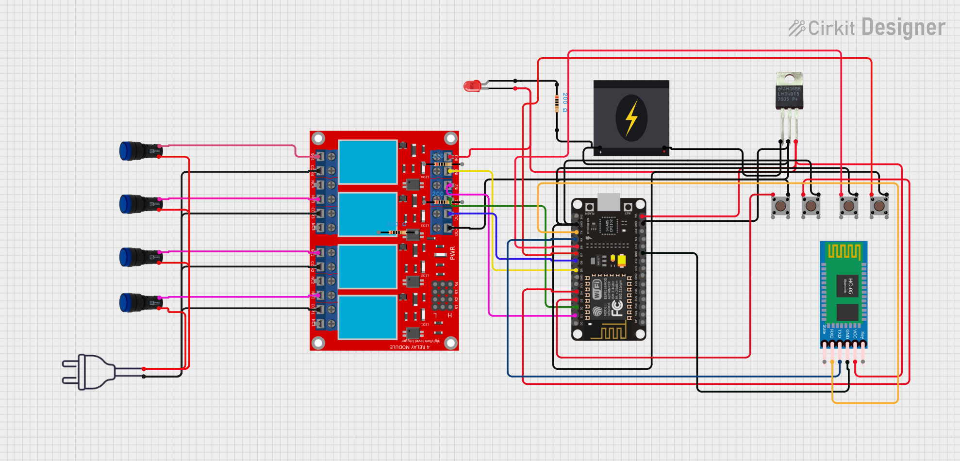

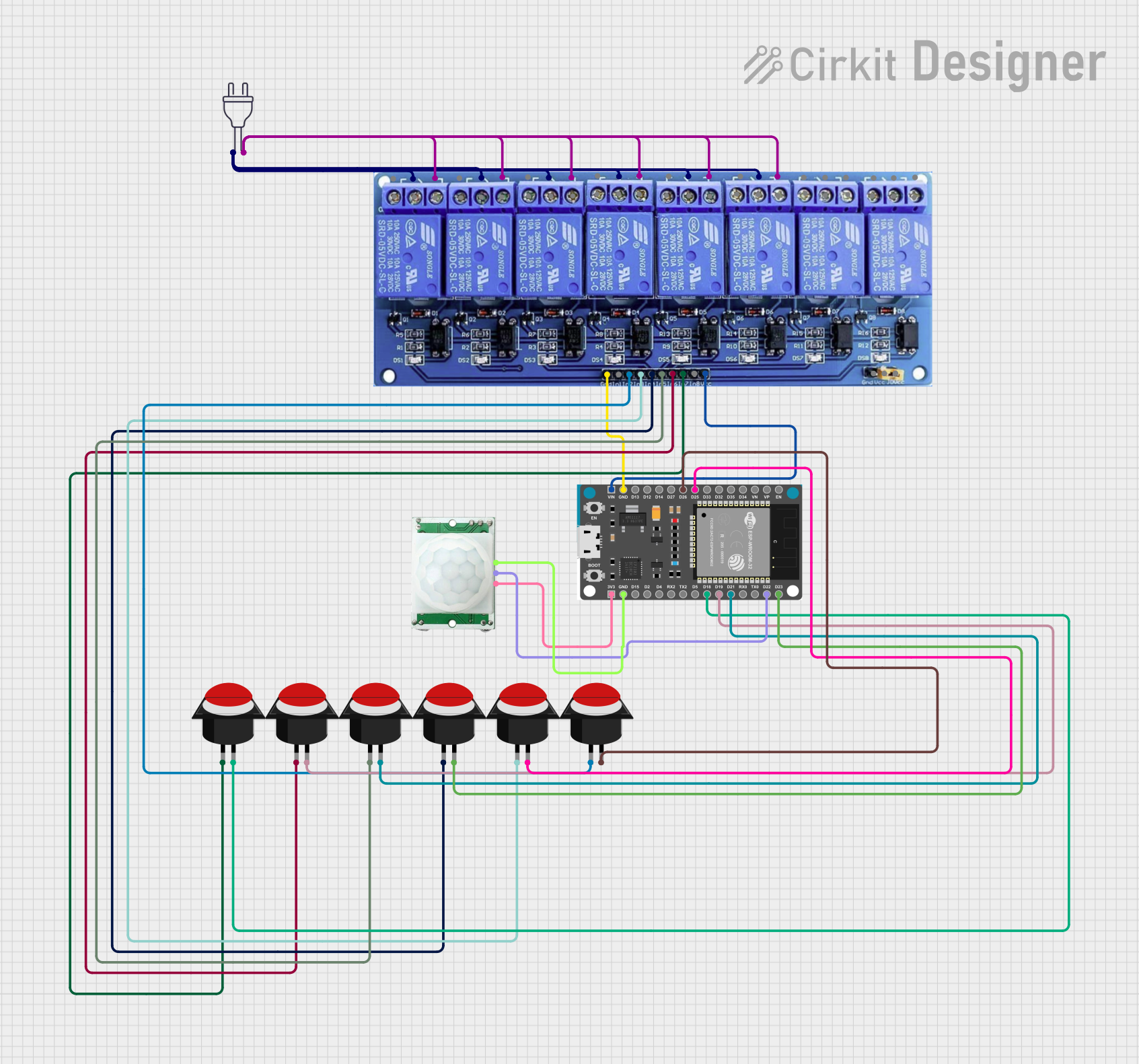
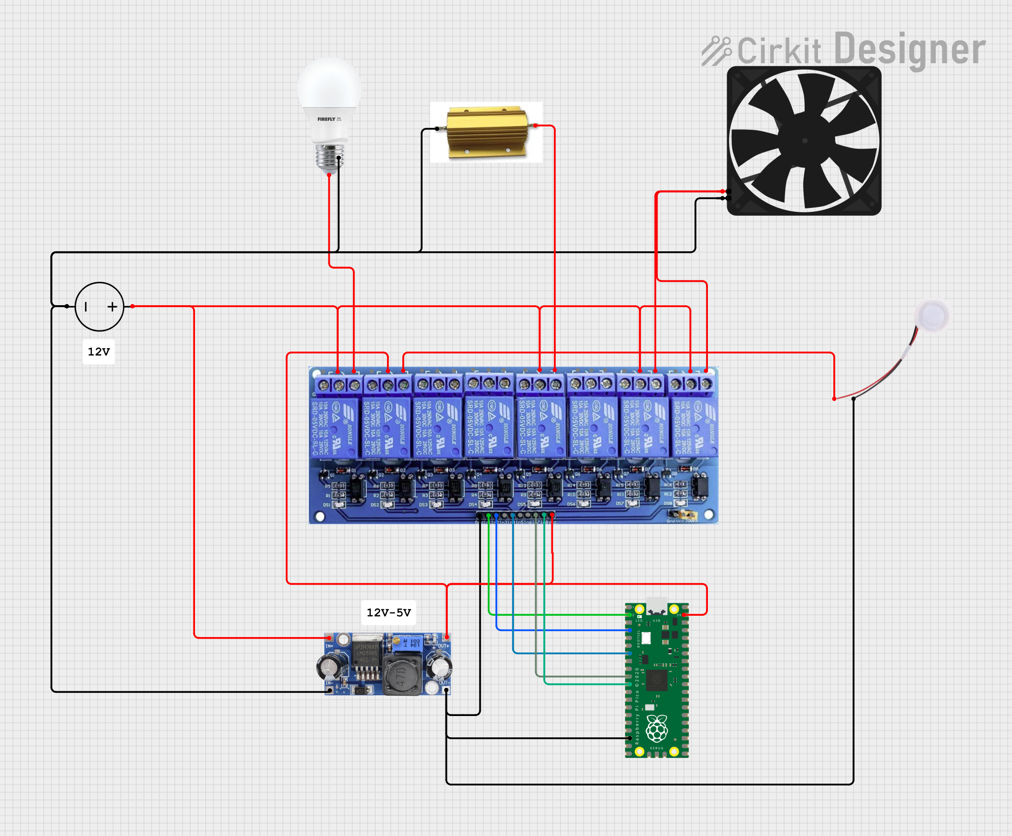
Explore Projects Built with PWM Relay
Common Applications and Use Cases
- Motor speed control in DC motors
- LED brightness adjustment
- Temperature regulation in heating elements
- Power control in industrial automation systems
- Battery charging systems with controlled current delivery
Technical Specifications
Key Technical Details
- Operating Voltage: 5V, 12V, or 24V (depending on the model)
- Control Signal: PWM input (typically 500 Hz to 10 kHz)
- Load Voltage: Up to 250V AC or 30V DC
- Load Current: Up to 10A (varies by model)
- Relay Type: SPDT (Single Pole Double Throw) or SPST (Single Pole Single Throw)
- PWM Duty Cycle Range: 0% to 100%
- Response Time: <10 ms
- Isolation: Optocoupler isolation for signal protection
Pin Configuration and Descriptions
The PWM relay typically has the following pin configuration:
| Pin Name | Description |
|---|---|
| VCC | Power supply input for the relay module (e.g., 5V, 12V, or 24V). |
| GND | Ground connection for the relay module. |
| PWM IN | PWM signal input to control the relay's switching behavior. |
| NO (Normally Open) | Normally open terminal for the load connection. |
| NC (Normally Closed) | Normally closed terminal for the load connection. |
| COM | Common terminal for the load connection. |
Usage Instructions
How to Use the Component in a Circuit
- Power the Relay Module: Connect the VCC and GND pins to the appropriate power supply (e.g., 5V, 12V, or 24V, depending on the relay model).
- Connect the Load:
- For devices that should be powered when the relay is active, connect the load between the NO (Normally Open) and COM (Common) terminals.
- For devices that should be powered when the relay is inactive, connect the load between the NC (Normally Closed) and COM terminals.
- Provide a PWM Signal: Connect the PWM signal source (e.g., a microcontroller like Arduino) to the PWM IN pin. The duty cycle of the PWM signal will control the relay's switching behavior.
- Adjust the Duty Cycle: Vary the duty cycle of the PWM signal to control the power delivered to the load. For example:
- A 50% duty cycle delivers half the power.
- A 100% duty cycle delivers full power.
Important Considerations and Best Practices
- Voltage Compatibility: Ensure the relay's operating voltage matches your power supply.
- PWM Frequency: Use a PWM frequency within the relay's specified range (typically 500 Hz to 10 kHz).
- Load Ratings: Do not exceed the relay's maximum load voltage or current ratings.
- Isolation: Use optocoupler isolation to protect sensitive control circuits from high-power loads.
- Heat Dissipation: If the relay operates at high currents, ensure proper ventilation or heat dissipation to prevent overheating.
Example: Using a PWM Relay with Arduino UNO
Below is an example of how to control a PWM relay using an Arduino UNO:
// Example: Controlling a PWM Relay with Arduino UNO
// This code generates a PWM signal on pin 9 to control the relay's duty cycle.

const int pwmPin = 9; // PWM output pin connected to the relay's PWM IN pin
int dutyCycle = 128;  // Initial duty cycle (50% of 255 for 8-bit PWM)

void setup() {
  pinMode(pwmPin, OUTPUT); // Set the PWM pin as an output
}

void loop() {
  analogWrite(pwmPin, dutyCycle); // Write the PWM signal to the relay
  delay(1000); // Keep the current duty cycle for 1 second

  // Increase the duty cycle by 10% every second
  dutyCycle += 26; // 26 is approximately 10% of 255
  if (dutyCycle > 255) {
    dutyCycle = 0; // Reset to 0% duty cycle after reaching 100%
  }
}
Troubleshooting and FAQs
Common Issues and Solutions
| Issue | Possible Cause | Solution |
|---|---|---|
| Relay does not switch on/off as expected. | Incorrect PWM signal frequency or duty cycle. | Verify that the PWM signal is within the specified frequency and duty cycle. |
| Load is not powered. | Incorrect wiring of the load to the relay terminals. | Double-check the connections to the NO, NC, and COM terminals. |
| Relay module overheats. | Exceeding the relay's current or voltage ratings. | Ensure the load does not exceed the relay's maximum ratings. |
| PWM signal not detected by the relay. | Insufficient voltage or current from the PWM source. | Use a stronger PWM signal or check the microcontroller's output settings. |
FAQs
Can I use a PWM relay with an AC load?
- Yes, as long as the load voltage and current are within the relay's AC ratings.
What happens if I use a PWM frequency outside the specified range?
- The relay may not respond correctly, leading to erratic switching or failure to operate.
Can I control multiple relays with a single microcontroller?
- Yes, as long as each relay is connected to a separate PWM-capable pin on the microcontroller.
Is optocoupler isolation necessary?
- While not mandatory, optocoupler isolation is highly recommended to protect the control circuit from high-power loads.
By following this documentation, you can effectively integrate a PWM relay into your projects for precise and efficient power control.