Cirkit Designer Logo
Cirkit Designer
Your all-in-one circuit design IDE
Home / 
Component Documentation

How to Use XH2.54-3P AUX: Examples, Pinouts, and Specs
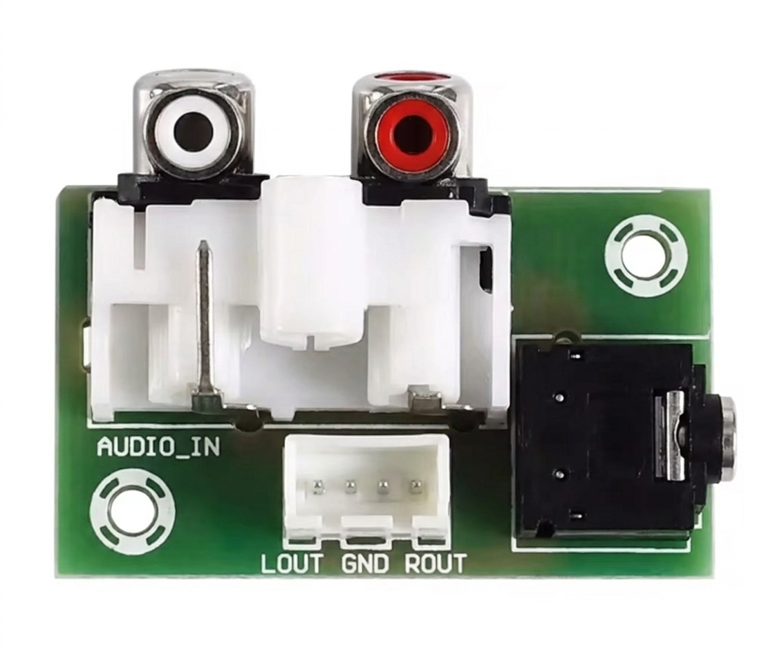

Image of XH2.54-3P AUX
Cirkit Designer LogoDesign with XH2.54-3P AUX in Cirkit Designer

Introduction

The XH2.54-3P AUX is a 3-pin connector widely used in electronic circuits for securely connecting wires to a printed circuit board (PCB). It features a 2.54mm pitch, making it compatible with standard breadboards and PCBs. This connector is known for its reliability, ease of use, and compact design, making it a popular choice in various applications.

Explore Projects Built with XH2.54-3P AUX

Use Cirkit Designer to design, explore, and prototype these projects online. Some projects support real-time simulation. Click "Open Project" to start designing instantly!
Satellite-Based Timing and Navigation System with SDR and Atomic Clock Synchronization
Image of GPS 시스템 측정 구성도_Confirm: A project utilizing XH2.54-3P AUX in a practical application
This circuit appears to be a complex system involving power supply management, GPS and timing synchronization, and data communication. It includes a SI-TEX G1 Satellite Compass for GPS data, an XHTF1021 Atomic Rubidium Clock for precise timing, and Ettus USRP B200 units for software-defined radio communication. Power is supplied through various SMPS units and distributed via terminal blocks and DC jacks. Data communication is facilitated by Beelink MINI S12 N95 computers, RS232 splitters, and a 1000BASE-T Media Converter for network connectivity. RF Directional Couplers are used to interface antennas with the USRP units, and the entire system is likely contained within cases for protection and organization.
Cirkit Designer LogoOpen Project in Cirkit Designer
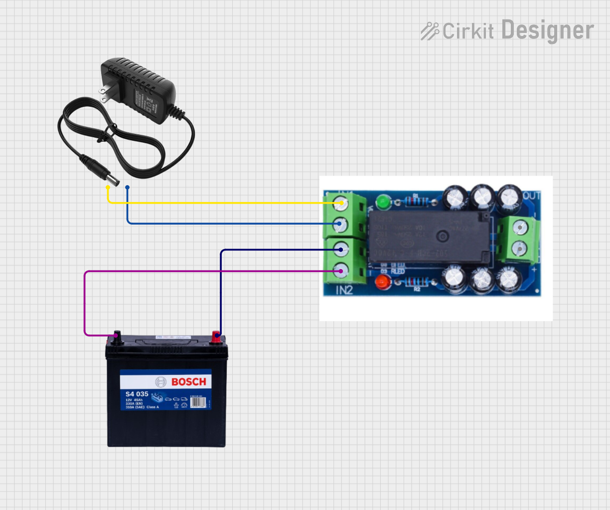
12V Power Supply with HX-M350 Backup Battery Switching
Image of power : A project utilizing XH2.54-3P AUX in a practical application
This circuit is designed to provide a backup power solution using a 12V 200Ah battery and a 12V power supply, with the HX-M350 module managing the switching between these power sources. The HX-M350 module automatically switches to the battery power when the main 12V power supply fails or is unavailable, ensuring uninterrupted power to the load. There is no microcontroller or additional control logic involved, indicating that the switching mechanism is likely handled entirely by the HX-M350 module itself.
Cirkit Designer LogoOpen Project in Cirkit Designer
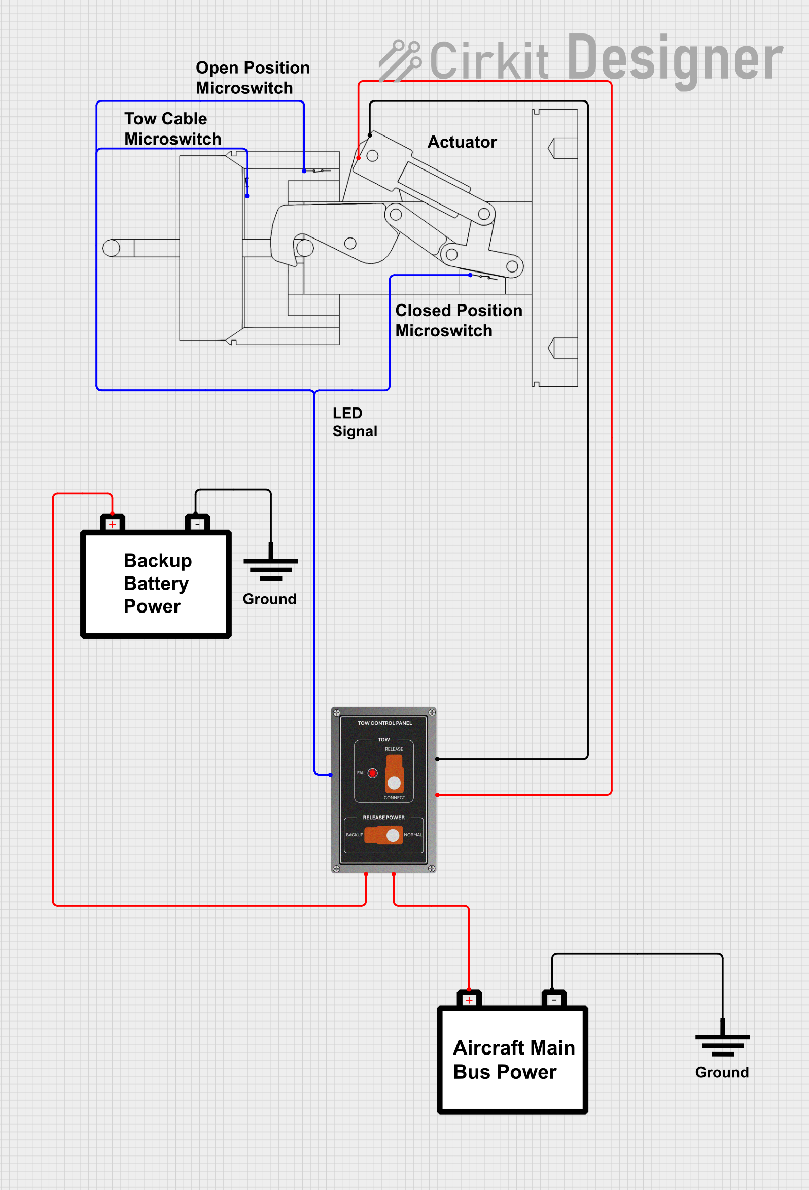
Aircraft Tow Release Control System with Dual Battery Backup
Image of Queen Air Tow Release Wiring: A project utilizing XH2.54-3P AUX in a practical application
This circuit is designed for a tow release control system in an aircraft, featuring a P68 Tow Control Panel and a Tow Release With Switches assembly. The control panel receives power from two separate aircraft batteries, with one providing main power and the other serving as a backup. The Tow Release With Switches assembly is connected to the control panel, allowing for the actuation of the tow mechanism and providing feedback via an LED indicator.
Cirkit Designer LogoOpen Project in Cirkit Designer
Satellite Compass and Network-Integrated GPS Data Processing System
Image of GPS 시스템 측정 구성도_241016: A project utilizing XH2.54-3P AUX in a practical application
This circuit comprises a satellite compass, a mini PC, two GPS antennas, power supplies, a network switch, media converters, and an atomic rubidium clock. The satellite compass is powered by a triple output DC power supply and interfaces with an RS232 splitter for 1PPS signals. The mini PCs are connected to the USRP B200 devices via USB for data and power, and to media converters via Ethernet, which in turn connect to a network switch using fiber optic links. The antennas are connected to the USRP B200s through RF directional couplers, and the atomic clock provides a 1PPS input to the RS232 splitter.
Cirkit Designer LogoOpen Project in Cirkit Designer

Explore Projects Built with XH2.54-3P AUX

Use Cirkit Designer to design, explore, and prototype these projects online. Some projects support real-time simulation. Click "Open Project" to start designing instantly!
Image of GPS 시스템 측정 구성도_Confirm: A project utilizing XH2.54-3P AUX in a practical application
Satellite-Based Timing and Navigation System with SDR and Atomic Clock Synchronization
This circuit appears to be a complex system involving power supply management, GPS and timing synchronization, and data communication. It includes a SI-TEX G1 Satellite Compass for GPS data, an XHTF1021 Atomic Rubidium Clock for precise timing, and Ettus USRP B200 units for software-defined radio communication. Power is supplied through various SMPS units and distributed via terminal blocks and DC jacks. Data communication is facilitated by Beelink MINI S12 N95 computers, RS232 splitters, and a 1000BASE-T Media Converter for network connectivity. RF Directional Couplers are used to interface antennas with the USRP units, and the entire system is likely contained within cases for protection and organization.
Cirkit Designer LogoOpen Project in Cirkit Designer
Image of power : A project utilizing XH2.54-3P AUX in a practical application
12V Power Supply with HX-M350 Backup Battery Switching
This circuit is designed to provide a backup power solution using a 12V 200Ah battery and a 12V power supply, with the HX-M350 module managing the switching between these power sources. The HX-M350 module automatically switches to the battery power when the main 12V power supply fails or is unavailable, ensuring uninterrupted power to the load. There is no microcontroller or additional control logic involved, indicating that the switching mechanism is likely handled entirely by the HX-M350 module itself.
Cirkit Designer LogoOpen Project in Cirkit Designer
Image of Queen Air Tow Release Wiring: A project utilizing XH2.54-3P AUX in a practical application
Aircraft Tow Release Control System with Dual Battery Backup
This circuit is designed for a tow release control system in an aircraft, featuring a P68 Tow Control Panel and a Tow Release With Switches assembly. The control panel receives power from two separate aircraft batteries, with one providing main power and the other serving as a backup. The Tow Release With Switches assembly is connected to the control panel, allowing for the actuation of the tow mechanism and providing feedback via an LED indicator.
Cirkit Designer LogoOpen Project in Cirkit Designer
Image of GPS 시스템 측정 구성도_241016: A project utilizing XH2.54-3P AUX in a practical application
Satellite Compass and Network-Integrated GPS Data Processing System
This circuit comprises a satellite compass, a mini PC, two GPS antennas, power supplies, a network switch, media converters, and an atomic rubidium clock. The satellite compass is powered by a triple output DC power supply and interfaces with an RS232 splitter for 1PPS signals. The mini PCs are connected to the USRP B200 devices via USB for data and power, and to media converters via Ethernet, which in turn connect to a network switch using fiber optic links. The antennas are connected to the USRP B200s through RF directional couplers, and the atomic clock provides a 1PPS input to the RS232 splitter.
Cirkit Designer LogoOpen Project in Cirkit Designer

Common Applications and Use Cases

  • Power supply connections in small electronic devices
  • Signal transmission between PCBs and external components
  • Prototyping and development of electronic circuits
  • Consumer electronics, such as home appliances and toys
  • Robotics and IoT projects

Technical Specifications

The XH2.54-3P AUX connector is designed to meet the needs of a wide range of electronic applications. Below are its key technical details:

Key Specifications

Parameter Value
Number of Pins 3
Pitch (Pin Spacing) 2.54mm
Rated Voltage 250V AC/DC
Rated Current 3A
Contact Resistance ≤ 20mΩ
Insulation Resistance ≥ 1000MΩ
Operating Temperature -25°C to +85°C
Material (Housing) Nylon 66 (UL94V-0 rated)
Material (Contacts) Tin-plated copper alloy

Pin Configuration and Descriptions

The XH2.54-3P AUX connector has three pins, typically used for power, ground, and signal connections. Below is the pinout description:

Pin Number Typical Function Description
1 VCC/Power Supplies power to the circuit
2 Signal Transmits data or control signals
3 GND Ground connection for the circuit

Usage Instructions

How to Use the XH2.54-3P AUX in a Circuit

  1. Soldering to a PCB:

    • Align the connector's pins with the corresponding holes on the PCB.
    • Solder each pin securely to ensure a reliable connection.
    • Avoid excessive soldering heat to prevent damage to the connector.
  2. Connecting Wires:

    • Use compatible crimp terminals or pre-crimped wires for a secure fit.
    • Insert the crimped wires into the connector housing until they click into place.
  3. Mating with a Header:

    • Ensure the mating header has a 2.54mm pitch and matches the pin configuration.
    • Gently push the connector onto the header until it is fully seated.

Important Considerations and Best Practices

  • Current and Voltage Ratings: Do not exceed the rated current (3A) or voltage (250V) to avoid overheating or damage.
  • Wire Gauge: Use wires with an appropriate gauge (typically 22-28 AWG) for optimal performance.
  • Secure Connections: Ensure all connections are tight to prevent intermittent contact or signal loss.
  • Polarity: Double-check the pin configuration to avoid reversing power and ground connections.

Example: Connecting to an Arduino UNO

The XH2.54-3P AUX connector can be used to connect external components, such as sensors or power supplies, to an Arduino UNO. Below is an example of how to use it for a simple LED circuit:

Circuit Description

  • Pin 1 (VCC) connects to the Arduino's 5V pin.
  • Pin 2 (Signal) connects to a digital output pin (e.g., D13).
  • Pin 3 (GND) connects to the Arduino's GND pin.

Arduino Code Example

// Simple LED Blink Example
// This code blinks an LED connected via the XH2.54-3P AUX connector.

// Define the pin connected to the LED
const int ledPin = 13;

void setup() {
  // Set the LED pin as an output
  pinMode(ledPin, OUTPUT);
}

void loop() {
  // Turn the LED on
  digitalWrite(ledPin, HIGH);
  delay(1000); // Wait for 1 second

  // Turn the LED off
  digitalWrite(ledPin, LOW);
  delay(1000); // Wait for 1 second
}

Troubleshooting and FAQs

Common Issues and Solutions

  1. Loose Connections:

    • Issue: The connector feels loose or wobbly.
    • Solution: Ensure the connector is fully seated on the mating header. Check for damaged pins or housing.
  2. Intermittent Signal Loss:

    • Issue: The circuit behaves erratically or loses signal.
    • Solution: Verify that all wires are securely crimped and inserted into the connector. Check for broken solder joints on the PCB.
  3. Overheating:

    • Issue: The connector becomes hot during operation.
    • Solution: Ensure the current and voltage do not exceed the rated limits. Use thicker wires if necessary.
  4. Incorrect Pinout:

    • Issue: The circuit does not function as expected.
    • Solution: Double-check the pin configuration and ensure proper connections to VCC, Signal, and GND.

FAQs

Q1: Can the XH2.54-3P AUX connector handle high-frequency signals?
A1: Yes, it can handle high-frequency signals, but for very high-speed applications, consider using shielded connectors to minimize interference.

Q2: Is the connector reusable?
A2: The connector housing is reusable, but crimp terminals may need to be replaced if removed frequently.

Q3: Can I use this connector for AC applications?
A3: Yes, it is rated for up to 250V AC, but ensure proper insulation and safety precautions are followed.

Q4: What tools are required for crimping wires?
A4: Use a compatible crimping tool designed for 2.54mm pitch connectors to achieve a secure and reliable connection.