How to Use AUX/RCA Board: Examples, Pinouts, and Specs
Introduction
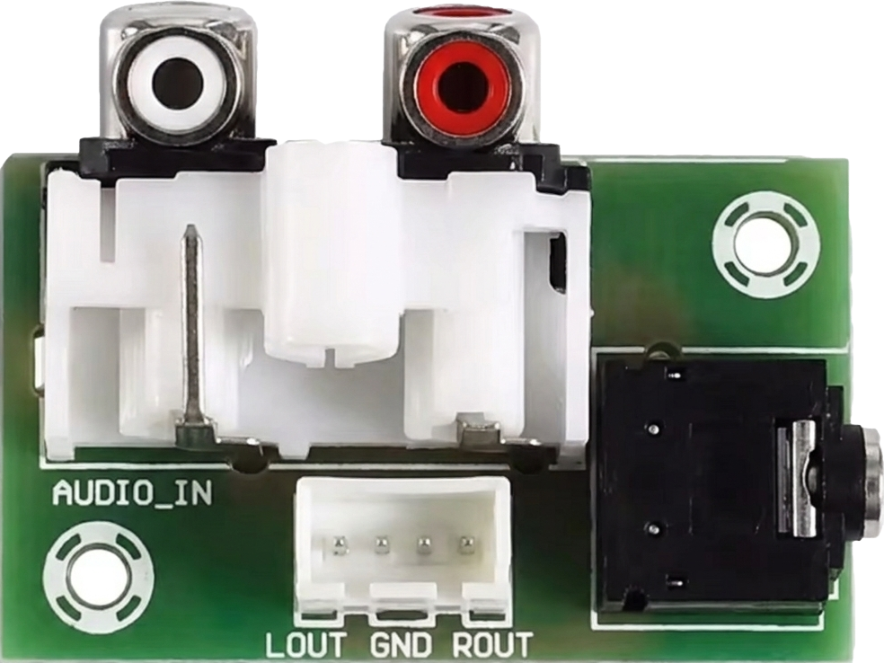
The AUX/RCA Board is a versatile circuit board designed to facilitate audio input connections via auxiliary (AUX) and RCA interfaces. This component allows users to integrate multiple audio sources, such as smartphones, media players, or other audio devices, into an audio system. It is commonly used in audio amplifiers, home theater systems, car audio setups, and DIY audio projects.
Explore Projects Built with AUX/RCA Board
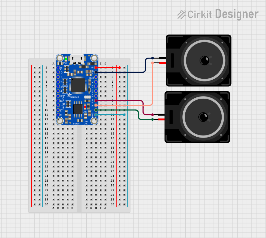


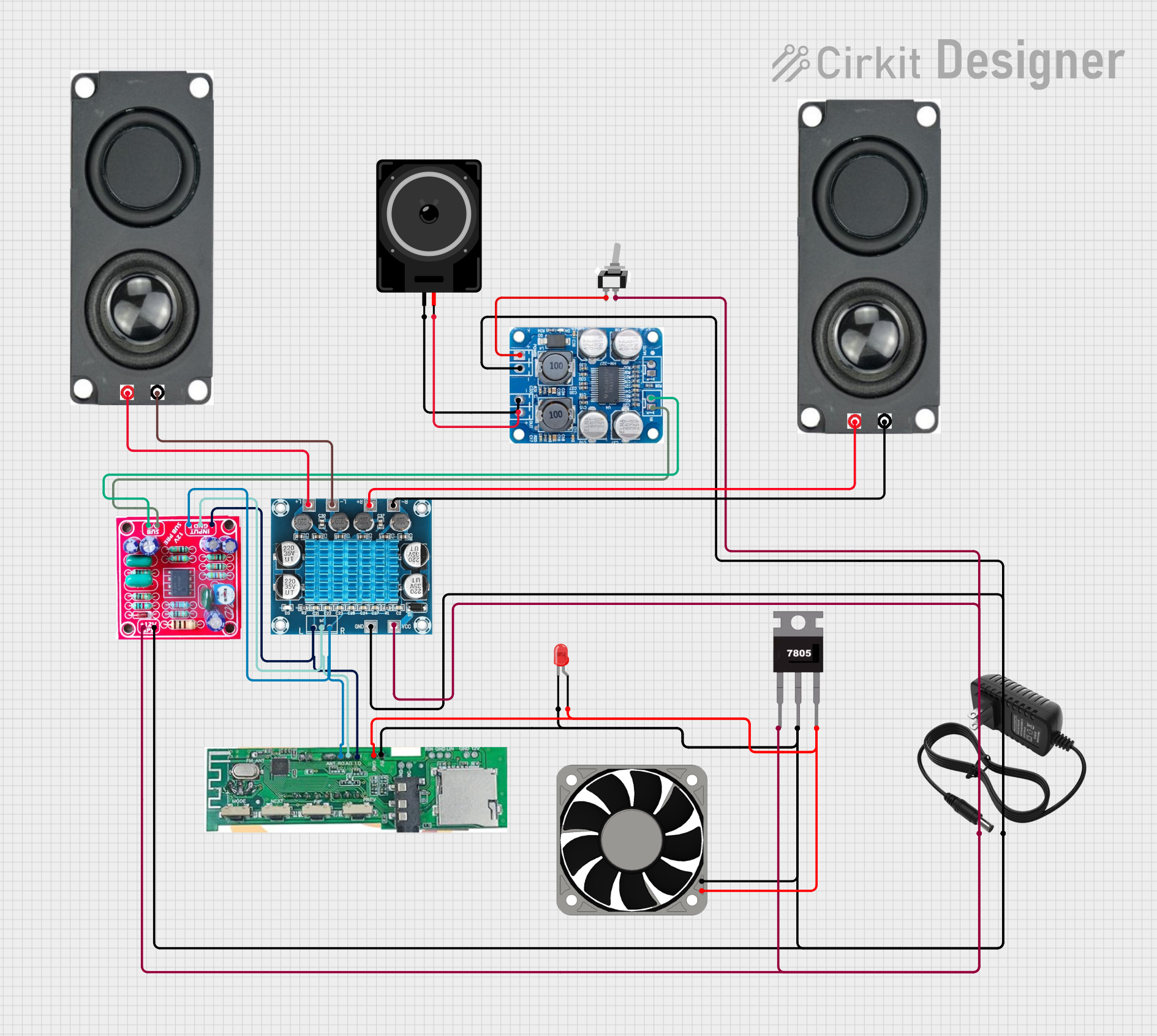
Explore Projects Built with AUX/RCA Board
Common Applications and Use Cases
- Connecting smartphones or MP3 players to audio amplifiers.
- Integrating RCA-based audio sources (e.g., DVD players, turntables) into sound systems.
- DIY audio projects requiring multiple input options.
- Car audio systems for auxiliary and RCA input integration.
Technical Specifications
The AUX/RCA Board is designed to handle low-power audio signals and provides a reliable interface for audio input. Below are the key technical details:
General Specifications
| Parameter | Value |
|---|---|
| Input Voltage | 5V to 12V (for optional power) |
| Signal Type | Stereo audio |
| Input Connectors | 3.5mm AUX jack, RCA (L/R) |
| Output Connector | Solder pads or pin headers |
| PCB Dimensions | Varies (e.g., 50mm x 30mm) |
| Supported Audio Range | 20Hz to 20kHz |
Pin Configuration and Descriptions
The board typically includes solder pads or pin headers for output connections. Below is a description of the pin configuration:
| Pin Name | Description |
|---|---|
| GND | Ground connection for the audio signal. |
| L_OUT | Left channel audio output. |
| R_OUT | Right channel audio output. |
| AUX_IN | Input from the 3.5mm AUX jack. |
| RCA_L_IN | Input from the RCA left channel. |
| RCA_R_IN | Input from the RCA right channel. |
| VCC (Optional) | Power input for active circuitry (if required). |
Usage Instructions
How to Use the AUX/RCA Board in a Circuit
Connect Audio Sources:
- Plug a 3.5mm AUX cable into the AUX jack for stereo audio input.
- Alternatively, connect RCA cables to the RCA input jacks for left and right channels.
Connect Outputs:
- Use the solder pads or pin headers to connect the
L_OUT,R_OUT, andGNDpins to the input of your audio amplifier or processing circuit.
- Use the solder pads or pin headers to connect the
Power the Board (if applicable):
- If the board includes active circuitry (e.g., preamplifiers), connect a 5V to 12V power source to the
VCCpin.
- If the board includes active circuitry (e.g., preamplifiers), connect a 5V to 12V power source to the
Test the Setup:
- Play audio from the connected source and verify that the output is clear and distortion-free.
Important Considerations and Best Practices
- Signal Grounding: Ensure that the ground (
GND) is properly connected to avoid noise or hum in the audio signal. - Cable Quality: Use high-quality AUX and RCA cables to minimize signal loss and interference.
- Power Supply: If the board requires external power, use a stable and noise-free power source to avoid introducing noise into the audio signal.
- Volume Levels: Avoid overdriving the input signal to prevent distortion.
Example: Connecting to an Arduino UNO
While the AUX/RCA Board is primarily for audio signal routing, it can be used with an Arduino UNO for audio signal detection or control. Below is an example of detecting audio signal levels using the Arduino's analog input:
// Example: Detecting audio signal levels from the AUX/RCA Board
// Connect L_OUT or R_OUT to Arduino analog pin A0
// Ensure GND from the board is connected to Arduino GND

const int audioPin = A0;  // Analog pin connected to audio output
int audioLevel = 0;       // Variable to store the audio signal level

void setup() {
  Serial.begin(9600);  // Initialize serial communication
  pinMode(audioPin, INPUT);  // Set the audio pin as input
}

void loop() {
  // Read the audio signal level (0-1023)
  audioLevel = analogRead(audioPin);

  // Print the audio level to the Serial Monitor
  Serial.print("Audio Level: ");
  Serial.println(audioLevel);

  delay(100);  // Small delay for readability
}
Troubleshooting and FAQs
Common Issues and Solutions
No Audio Output:
- Verify that the audio source is properly connected to the AUX or RCA inputs.
- Check the connections to the output pins (
L_OUT,R_OUT, andGND). - Ensure the board is powered if it includes active circuitry.
Distorted Audio:
- Reduce the volume of the audio source to avoid overdriving the input.
- Check for loose or poor-quality cables.
Noise or Hum in the Audio:
- Ensure proper grounding of the circuit.
- Use shielded cables to minimize interference.
Low Audio Signal:
- If the output signal is too weak, consider using a preamplifier circuit.
FAQs
Q: Can I use both AUX and RCA inputs simultaneously?
A: It is not recommended to use both inputs simultaneously, as this may cause signal interference. Use one input at a time for optimal performance.
Q: Does the board amplify the audio signal?
A: Most AUX/RCA boards are passive and do not amplify the signal. If amplification is required, use an external preamplifier or amplifier.
Q: Can I connect the board directly to speakers?
A: No, the board outputs a low-level audio signal that must be connected to an amplifier before driving speakers.
Q: What is the maximum cable length for AUX or RCA connections?
A: For best performance, keep cable lengths under 3 meters to minimize signal loss and interference.
This concludes the documentation for the AUX/RCA Board.