How to Use IR Obstacle Avoidance Sensor: Examples, Pinouts, and Specs
Introduction
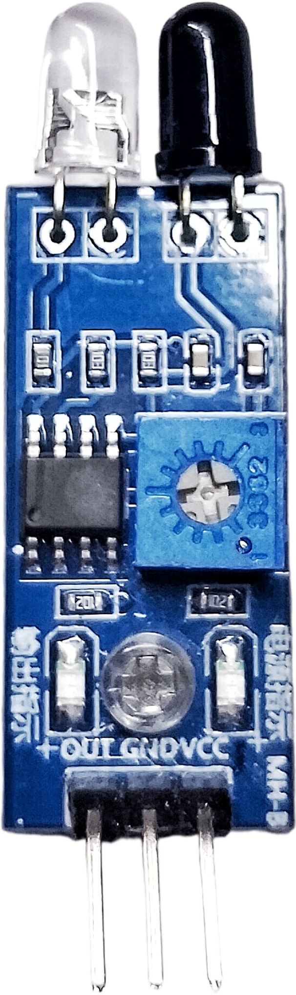
The IR Obstacle Avoidance Sensor is a compact and efficient module designed to detect obstacles using infrared (IR) light. It emits IR light and measures the reflected signal to determine the presence of an object within its detection range. This sensor is widely used in robotics, automation systems, and other applications requiring obstacle detection and avoidance.
Explore Projects Built with IR Obstacle Avoidance Sensor
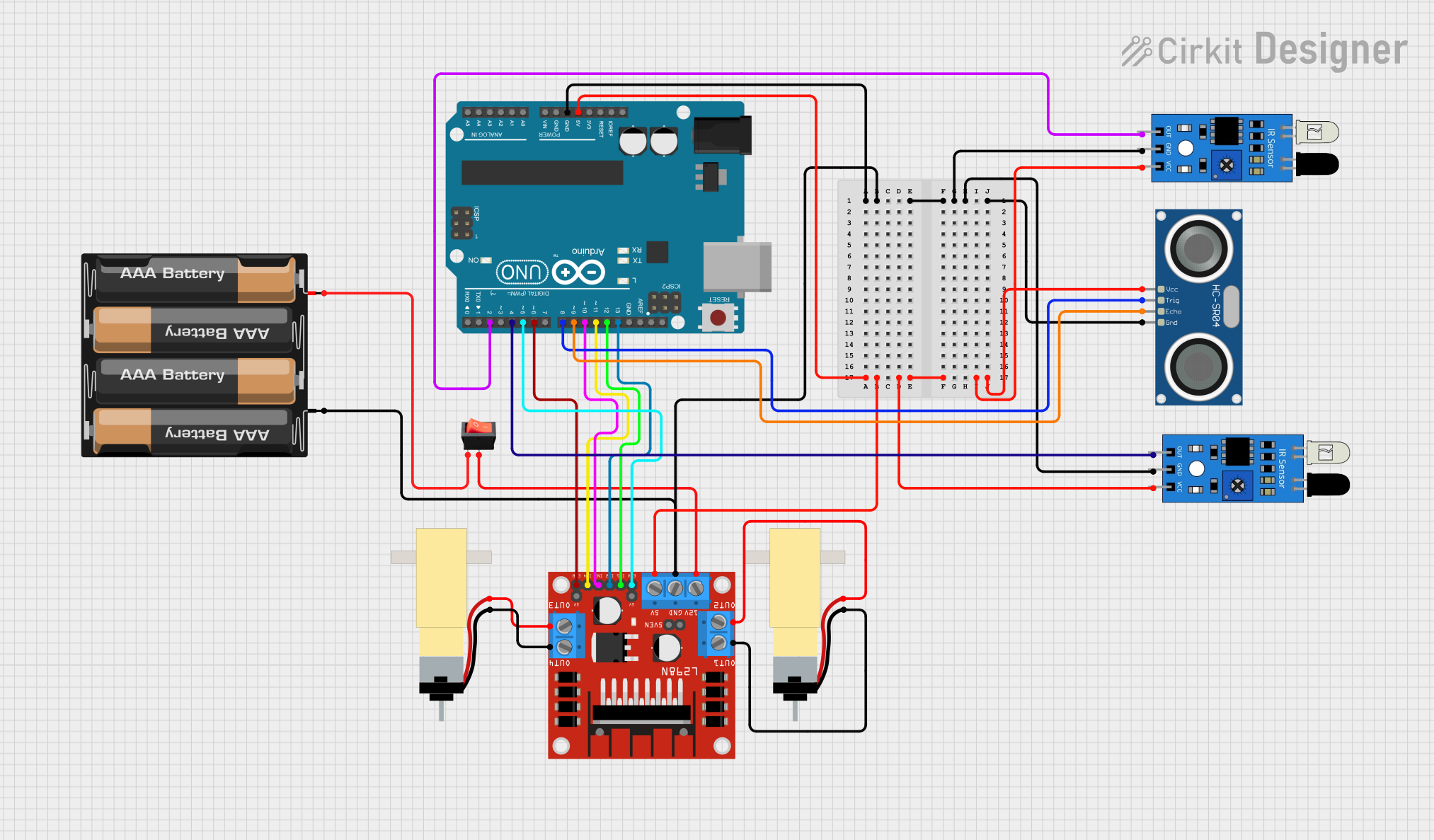
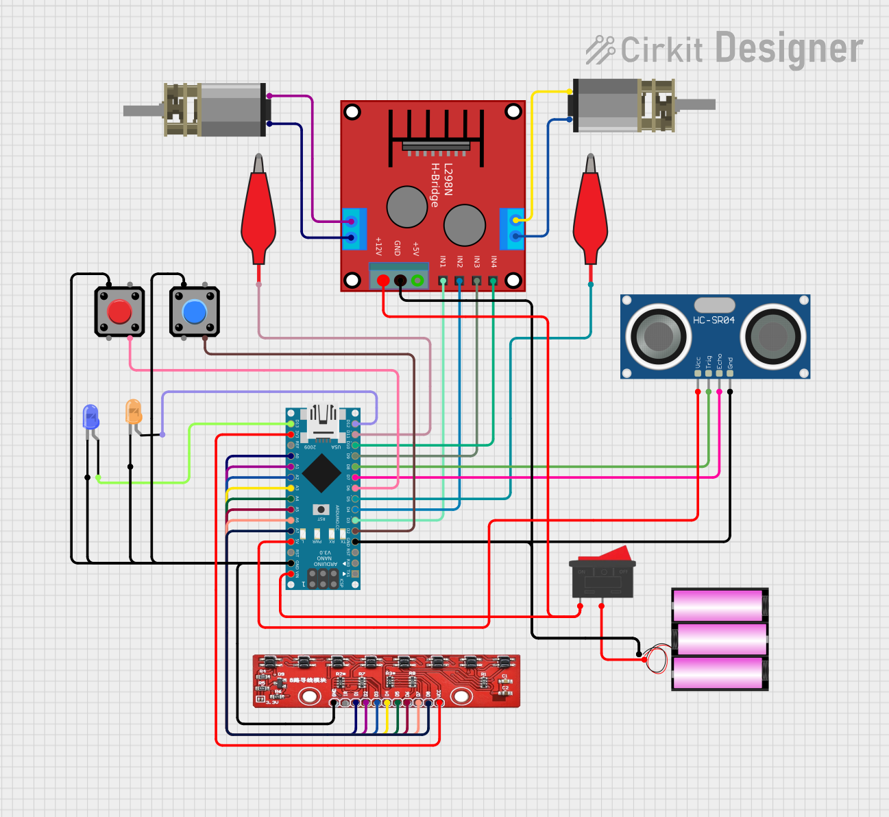
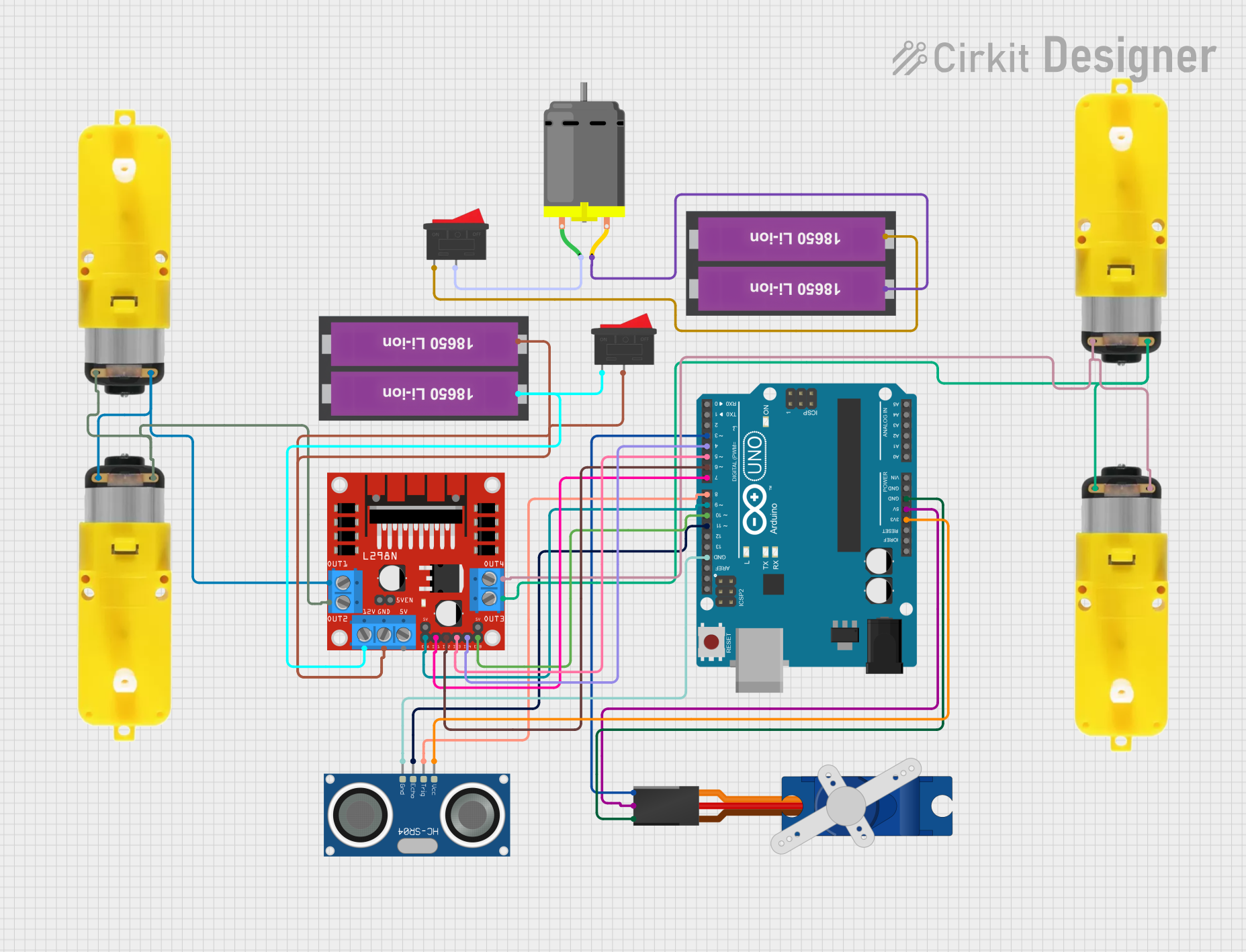
Explore Projects Built with IR Obstacle Avoidance Sensor
Common Applications and Use Cases
- Autonomous robots for navigation and collision avoidance
- Line-following robots
- Object detection in conveyor systems
- Proximity sensing in smart devices
- Security systems for detecting intrusions
Technical Specifications
The following table outlines the key technical details of the IR Obstacle Avoidance Sensor:
| Parameter | Value |
|---|---|
| Operating Voltage | 3.3V to 5V |
| Operating Current | 20mA (typical) |
| Detection Range | 2cm to 30cm (adjustable) |
| Detection Angle | ≤ 35° |
| Output Type | Digital (High/Low) |
| Dimensions | ~3.1cm x 1.5cm x 0.7cm |
| Operating Temperature | -10°C to 50°C |
Pin Configuration and Descriptions
The IR Obstacle Avoidance Sensor typically has a 3-pin or 4-pin interface. Below is the pinout description:
3-Pin Version
| Pin | Name | Description |
|---|---|---|
| 1 | VCC | Power supply input (3.3V to 5V) |
| 2 | GND | Ground connection |
| 3 | OUT | Digital output signal (High: No obstacle, Low: Obstacle detected) |
4-Pin Version
| Pin | Name | Description |
|---|---|---|
| 1 | VCC | Power supply input (3.3V to 5V) |
| 2 | GND | Ground connection |
| 3 | OUT | Digital output signal (High: No obstacle, Low: Obstacle detected) |
| 4 | EN | Enable pin (optional, used to enable/disable the sensor) |
Usage Instructions
How to Use the Component in a Circuit
- Power the Sensor: Connect the VCC pin to a 3.3V or 5V power source and the GND pin to the ground.
- Connect the Output: Attach the OUT pin to a digital input pin of your microcontroller or logic circuit.
- Adjust the Sensitivity: Use the onboard potentiometer to adjust the detection range. Turn clockwise to increase the range and counterclockwise to decrease it.
- Test the Sensor: Place an object within the detection range and observe the output signal. The OUT pin will go LOW when an obstacle is detected.
Important Considerations and Best Practices
- Avoid Direct Sunlight: IR sensors can be affected by strong ambient light. Use the sensor in controlled lighting conditions for optimal performance.
- Mounting Position: Ensure the sensor is mounted at an appropriate angle to detect obstacles effectively.
- Power Supply: Use a stable power source to avoid erratic behavior.
- Interference: Avoid placing multiple IR sensors too close to each other, as their signals may interfere.
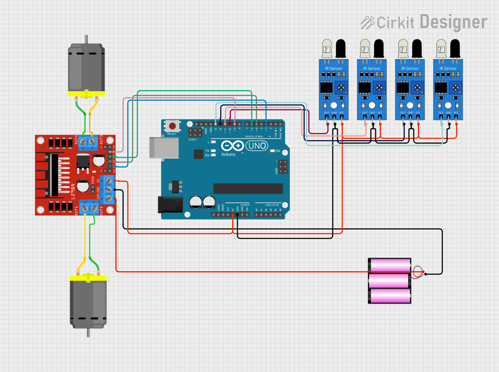
Example: Connecting to an Arduino UNO
Below is an example of how to connect and use the IR Obstacle Avoidance Sensor with an Arduino UNO:
Circuit Connections
- VCC: Connect to the 5V pin on the Arduino.
- GND: Connect to the GND pin on the Arduino.
- OUT: Connect to digital pin 2 on the Arduino.
Arduino Code
// IR Obstacle Avoidance Sensor Example Code
// Connect the OUT pin of the sensor to Arduino digital pin 2

const int sensorPin = 2;  // Pin connected to the sensor's OUT pin
const int ledPin = 13;    // Built-in LED on Arduino

void setup() {
  pinMode(sensorPin, INPUT);  // Set sensor pin as input
  pinMode(ledPin, OUTPUT);    // Set LED pin as output
  Serial.begin(9600);         // Initialize serial communication
}

void loop() {
  int sensorValue = digitalRead(sensorPin);  // Read the sensor output

  if (sensorValue == LOW) {
    // Obstacle detected
    digitalWrite(ledPin, HIGH);  // Turn on the LED
    Serial.println("Obstacle detected!");
  } else {
    // No obstacle
    digitalWrite(ledPin, LOW);   // Turn off the LED
    Serial.println("No obstacle.");
  }

  delay(100);  // Small delay for stability
}
Troubleshooting and FAQs
Common Issues and Solutions
Sensor Not Detecting Obstacles
- Cause: Incorrect sensitivity setting.
- Solution: Adjust the potentiometer to modify the detection range.
False Positives in Bright Light
- Cause: Strong ambient light interfering with the IR signal.
- Solution: Use the sensor in a shaded environment or add an IR filter.
No Output Signal
- Cause: Loose or incorrect wiring.
- Solution: Double-check all connections and ensure the power supply is stable.
Interference Between Multiple Sensors
- Cause: Overlapping IR signals from nearby sensors.
- Solution: Space the sensors apart or use shielding to isolate their signals.
FAQs
Q: Can this sensor detect transparent objects?
A: No, the sensor may not reliably detect transparent or highly reflective objects due to insufficient IR reflection.
Q: What is the maximum detection range?
A: The sensor can detect objects up to 30cm, depending on the object's size, color, and reflectivity.
Q: Can I use this sensor with a 3.3V microcontroller?
A: Yes, the sensor operates within a voltage range of 3.3V to 5V, making it compatible with 3.3V systems.
Q: How do I know if the sensor is working?
A: Most IR Obstacle Avoidance Sensors have an onboard LED that lights up when an obstacle is detected. Additionally, you can monitor the OUT pin for a LOW signal.