Cirkit Designer Logo
Cirkit Designer
Your all-in-one circuit design IDE
Home / 
Component Documentation

How to Use Raspberry Pi Pico Board RP2040: Examples, Pinouts, and Specs

Image of Raspberry Pi Pico Board RP2040
Cirkit Designer LogoDesign with Raspberry Pi Pico Board RP2040 in Cirkit Designer

Introduction

The Raspberry Pi Pico Board RP2040 is a compact and versatile microcontroller board developed by Raspberry. It is powered by the RP2040 chip, a dual-core ARM Cortex-M0+ processor, and is designed for a wide range of applications, from simple hobbyist projects to complex embedded systems. The board features 26 GPIO pins, USB connectivity, and supports programming in C, C++, MicroPython, and CircuitPython, making it an excellent choice for both beginners and experienced developers.

Explore Projects Built with Raspberry Pi Pico Board RP2040

Use Cirkit Designer to design, explore, and prototype these projects online. Some projects support real-time simulation. Click "Open Project" to start designing instantly!
Raspberry Pi Pico-Based Navigation Assistant with Bluetooth and GPS
Image of sat_dish: compass example: A project utilizing Raspberry Pi Pico Board RP2040 in a practical application
This circuit features a Raspberry Pi Pico microcontroller interfaced with an HC-05 Bluetooth module for wireless communication, an HMC5883L compass module for magnetic field measurement, and a GPS NEO 6M module for location tracking. The Pico is configured to communicate with the HC-05 via serial connection (TX/RX), with the compass module via I2C (SCL/SDA), and with the GPS module via serial (TX/RX). Common power (VCC) and ground (GND) lines are shared among all modules, indicating a unified power system.
Cirkit Designer LogoOpen Project in Cirkit Designer
Raspberry Pi Pico and RP2040-Based Multi-Color LED Control with MPU6050 Integration
Image of ast_v2_diagram: A project utilizing Raspberry Pi Pico Board RP2040 in a practical application
This circuit features a Raspberry Pi Pico and an RP2040 microcontroller interfacing with two MPU6050 sensors for motion tracking. It also includes multiple LEDs (red, green, and blue) connected through resistors, likely for status indication or visual feedback.
Cirkit Designer LogoOpen Project in Cirkit Designer
Raspberry Pi Pico and OV7670 Camera-Based Robotic System with TFT Display
Image of REF Speed Bot V3 CKT: A project utilizing Raspberry Pi Pico Board RP2040 in a practical application
This circuit features two Raspberry Pi Pico microcontrollers interfacing with various peripherals including an OV7670 camera module, a TFT display, and an OLED display. It also includes a multiplexer and a motor driver to control two planetary gearbox motors, powered by a battery and regulated through buck converters. The setup is designed for image capture, display, and motor control applications.
Cirkit Designer LogoOpen Project in Cirkit Designer
Raspberry Pi Pico-Based Navigation System with Bluetooth and GPS
Image of sat_dish: pwm application: A project utilizing Raspberry Pi Pico Board RP2040 in a practical application
This circuit features a Raspberry Pi Pico microcontroller interfaced with multiple peripherals for navigation and control. It includes an HC-05 Bluetooth module for wireless communication, an HMC5883L compass for magnetic heading detection, a GPS NEO 6M module for location tracking, and an SG90 servomotor for actuation. The Pico manages data exchange with the GPS and compass via serial connections, controls the servomotor, and communicates wirelessly through the HC-05 module.
Cirkit Designer LogoOpen Project in Cirkit Designer

Explore Projects Built with Raspberry Pi Pico Board RP2040

Use Cirkit Designer to design, explore, and prototype these projects online. Some projects support real-time simulation. Click "Open Project" to start designing instantly!
Image of sat_dish: compass example: A project utilizing Raspberry Pi Pico Board RP2040 in a practical application
Raspberry Pi Pico-Based Navigation Assistant with Bluetooth and GPS
This circuit features a Raspberry Pi Pico microcontroller interfaced with an HC-05 Bluetooth module for wireless communication, an HMC5883L compass module for magnetic field measurement, and a GPS NEO 6M module for location tracking. The Pico is configured to communicate with the HC-05 via serial connection (TX/RX), with the compass module via I2C (SCL/SDA), and with the GPS module via serial (TX/RX). Common power (VCC) and ground (GND) lines are shared among all modules, indicating a unified power system.
Cirkit Designer LogoOpen Project in Cirkit Designer
Image of ast_v2_diagram: A project utilizing Raspberry Pi Pico Board RP2040 in a practical application
Raspberry Pi Pico and RP2040-Based Multi-Color LED Control with MPU6050 Integration
This circuit features a Raspberry Pi Pico and an RP2040 microcontroller interfacing with two MPU6050 sensors for motion tracking. It also includes multiple LEDs (red, green, and blue) connected through resistors, likely for status indication or visual feedback.
Cirkit Designer LogoOpen Project in Cirkit Designer
Image of REF Speed Bot V3 CKT: A project utilizing Raspberry Pi Pico Board RP2040 in a practical application
Raspberry Pi Pico and OV7670 Camera-Based Robotic System with TFT Display
This circuit features two Raspberry Pi Pico microcontrollers interfacing with various peripherals including an OV7670 camera module, a TFT display, and an OLED display. It also includes a multiplexer and a motor driver to control two planetary gearbox motors, powered by a battery and regulated through buck converters. The setup is designed for image capture, display, and motor control applications.
Cirkit Designer LogoOpen Project in Cirkit Designer
Image of sat_dish: pwm application: A project utilizing Raspberry Pi Pico Board RP2040 in a practical application
Raspberry Pi Pico-Based Navigation System with Bluetooth and GPS
This circuit features a Raspberry Pi Pico microcontroller interfaced with multiple peripherals for navigation and control. It includes an HC-05 Bluetooth module for wireless communication, an HMC5883L compass for magnetic heading detection, a GPS NEO 6M module for location tracking, and an SG90 servomotor for actuation. The Pico manages data exchange with the GPS and compass via serial connections, controls the servomotor, and communicates wirelessly through the HC-05 module.
Cirkit Designer LogoOpen Project in Cirkit Designer

Common Applications and Use Cases

  • IoT (Internet of Things) devices and automation
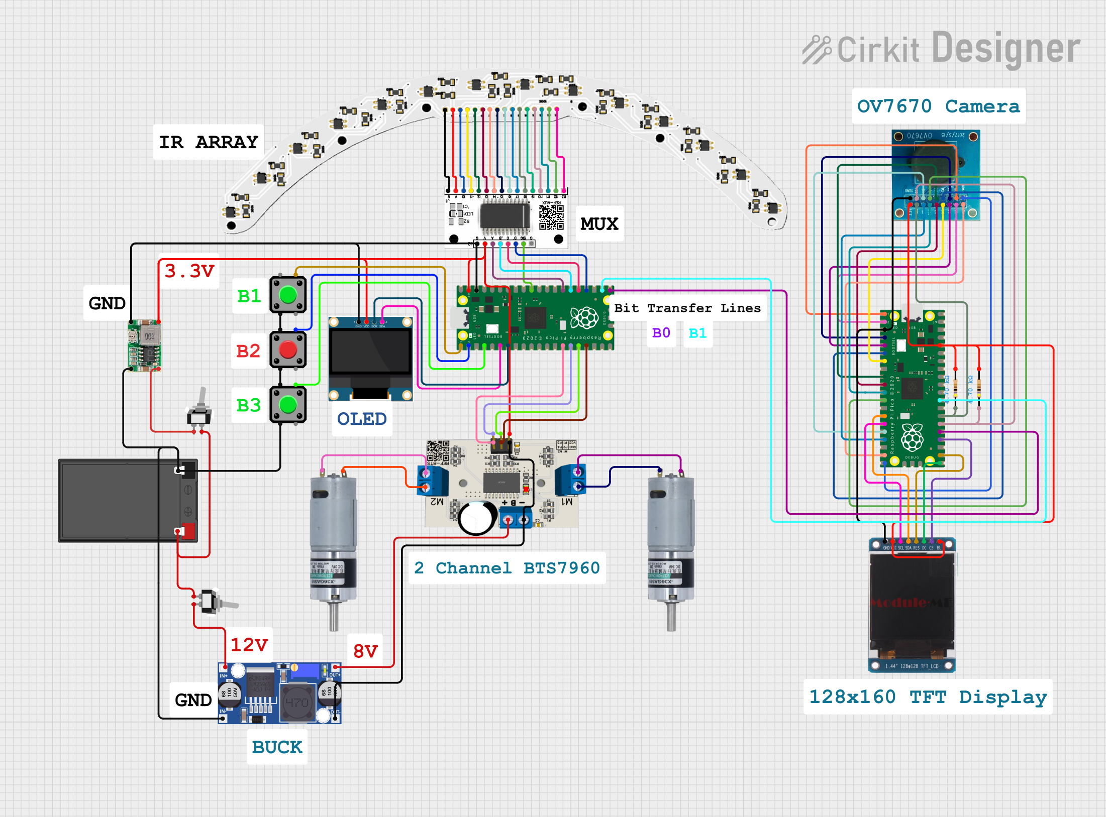
  • Robotics and motor control
  • Sensor interfacing and data logging
  • Educational projects and prototyping
  • Wearable electronics
  • Home automation systems

Technical Specifications

Key Technical Details

  • Processor: Dual-core ARM Cortex-M0+ @ 133 MHz
  • Memory: 264 KB SRAM, 2 MB onboard QSPI flash
  • GPIO Pins: 26 multi-function pins (3.3V logic level)
  • Interfaces: I2C, SPI, UART, PWM, ADC
  • USB: Micro-USB port for power, programming, and communication
  • Operating Voltage: 3.3V (GPIO), 5V (via USB or VSYS pin)
  • Power Supply: 1.8V to 5.5V (via VSYS pin)
  • Dimensions: 51mm x 21mm
  • Temperature Range: -20°C to +85°C

Pin Configuration and Descriptions

The Raspberry Pi Pico Board RP2040 has 40 pins, including power, ground, and GPIO pins. Below is a summary of the pin configuration:

Pin Number Pin Name Description
1 GND Ground
2 VSYS Power input (1.8V to 5.5V)
3 GND Ground
4 3V3(OUT) 3.3V output
5 GP0 GPIO 0, supports I2C0 SDA, SPI0 RX
6 GP1 GPIO 1, supports I2C0 SCL, SPI0 CSn
7 GND Ground
8 GP2 GPIO 2, supports I2C1 SDA, SPI0 SCK
9 GP3 GPIO 3, supports I2C1 SCL, SPI0 TX
10 GND Ground
... ... ... (Refer to the official datasheet for full details)

For a complete pinout diagram, refer to the official Raspberry Pi Pico documentation.

Usage Instructions

How to Use the Raspberry Pi Pico Board RP2040 in a Circuit

  1. Powering the Board:

    • Connect the board to a computer or USB power source using a Micro-USB cable.
    • Alternatively, supply power via the VSYS pin (1.8V to 5.5V).
  2. Programming the Board:

    • Install the required software (e.g., Thonny IDE for MicroPython or the Arduino IDE for C/C++).
    • Put the board into bootloader mode by holding the BOOTSEL button while connecting it to your computer via USB.
    • Drag and drop the firmware file (e.g., MicroPython UF2) onto the mounted drive.
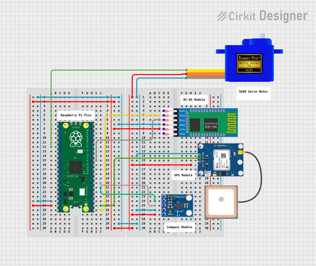
  3. Connecting Peripherals:

    • Use the GPIO pins to connect sensors, actuators, or other peripherals.
    • Ensure that all connected devices operate at 3.3V logic levels to avoid damaging the board.
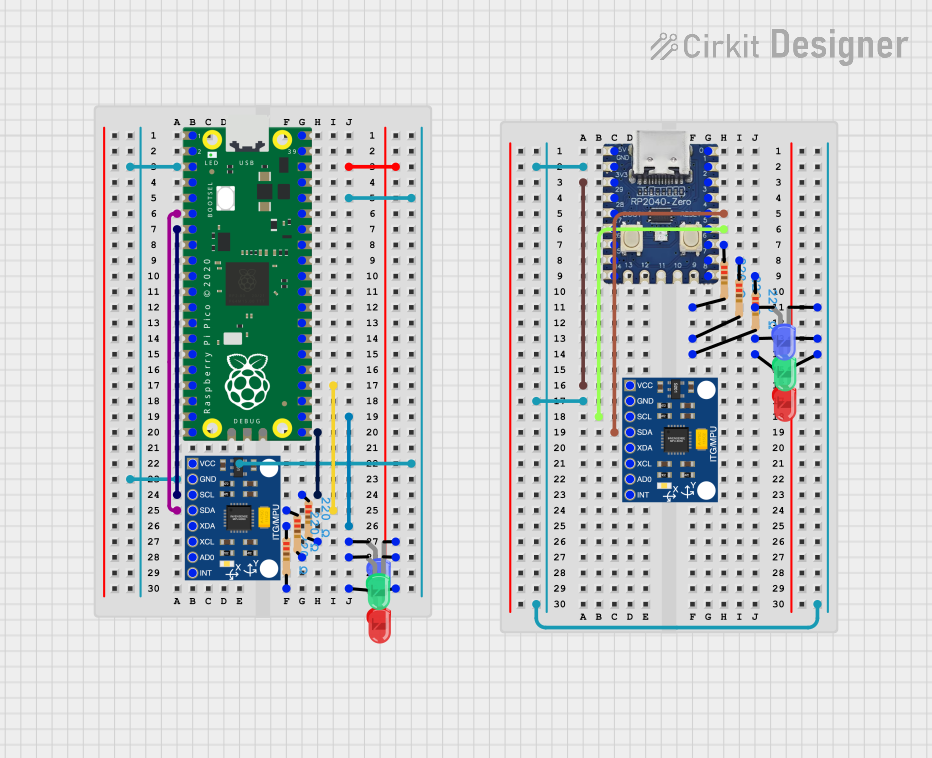
  4. Example Circuit:

    • Connect an LED to GPIO 15 with a 330-ohm resistor in series.
    • Use the following MicroPython code to blink the LED.

Example MicroPython Code


Import the Pin and Timer classes from the machine module

from machine import Pin, Timer

Configure GPIO 15 as an output pin

led = Pin(15, Pin.OUT)

Define a function to toggle the LED state

def toggle_led(timer): led.toggle() # Toggle the LED on/off

Create a timer to call the toggle_led function every 500ms

timer = Timer() timer.init(freq=2, mode=Timer.PERIODIC, callback=toggle_led)

The LED will now blink at a frequency of 2 Hz (500ms on/off)


Important Considerations and Best Practices

  • Always check the voltage and current ratings of connected peripherals to avoid damage.
  • Use level shifters if interfacing with 5V devices.
  • Avoid shorting GPIO pins or connecting them directly to power or ground.
  • Use decoupling capacitors for stable power supply in noisy environments.

Troubleshooting and FAQs

Common Issues and Solutions

  1. The board is not detected by the computer:

    • Ensure the Micro-USB cable supports data transfer (not just charging).
    • Check if the board is in bootloader mode (hold BOOTSEL while connecting).
  2. GPIO pins are not working as expected:

    • Verify the pin configuration in your code.
    • Check for loose or incorrect connections in the circuit.
  3. The board overheats or shuts down:

    • Ensure the power supply voltage is within the acceptable range (1.8V to 5.5V).
    • Avoid drawing excessive current from the GPIO pins.

FAQs

  • Can I power the board with a battery?
    Yes, you can power the board using a battery connected to the VSYS pin, as long as the voltage is between 1.8V and 5.5V.

  • What programming languages are supported?
    The Raspberry Pi Pico supports C, C++, MicroPython, and CircuitPython.

  • How do I reset the board?
    Disconnect and reconnect the power, or press the reset button if available.

For more detailed information, refer to the official Raspberry Pi Pico documentation.