Cirkit Designer
Your all-in-one circuit design IDE
Home /
Component Documentation
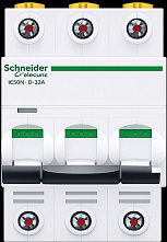
How to Use MCB 3P: Examples, Pinouts, and Specs
Introduction
- The MCB 3P (Miniature Circuit Breaker, 3-pole) is an essential safety device designed to protect electrical circuits from overloads and short circuits. It automatically disconnects the circuit when a fault is detected, preventing damage to equipment and reducing the risk of fire or electrical hazards.
- Commonly used in industrial, commercial, and residential electrical systems, the MCB 3P is ideal for three-phase power distribution systems. It ensures reliable protection for motors, lighting systems, and other electrical loads.
Explore Projects Built with MCB 3P
Solar-Powered Home Energy System with Automatic Transfer Switch and Battery Backup

This circuit is a solar power system with an automatic transfer switch (ATS) that manages power from both a solar panel and an AC supply. The solar panel charges a battery through a solar charge controller, and the power inverter converts the stored DC power to AC, which is then distributed through an MCB to a socket. The ATS ensures seamless switching between solar and AC power sources.
Solar-Powered UPS with Multiple Battery Management
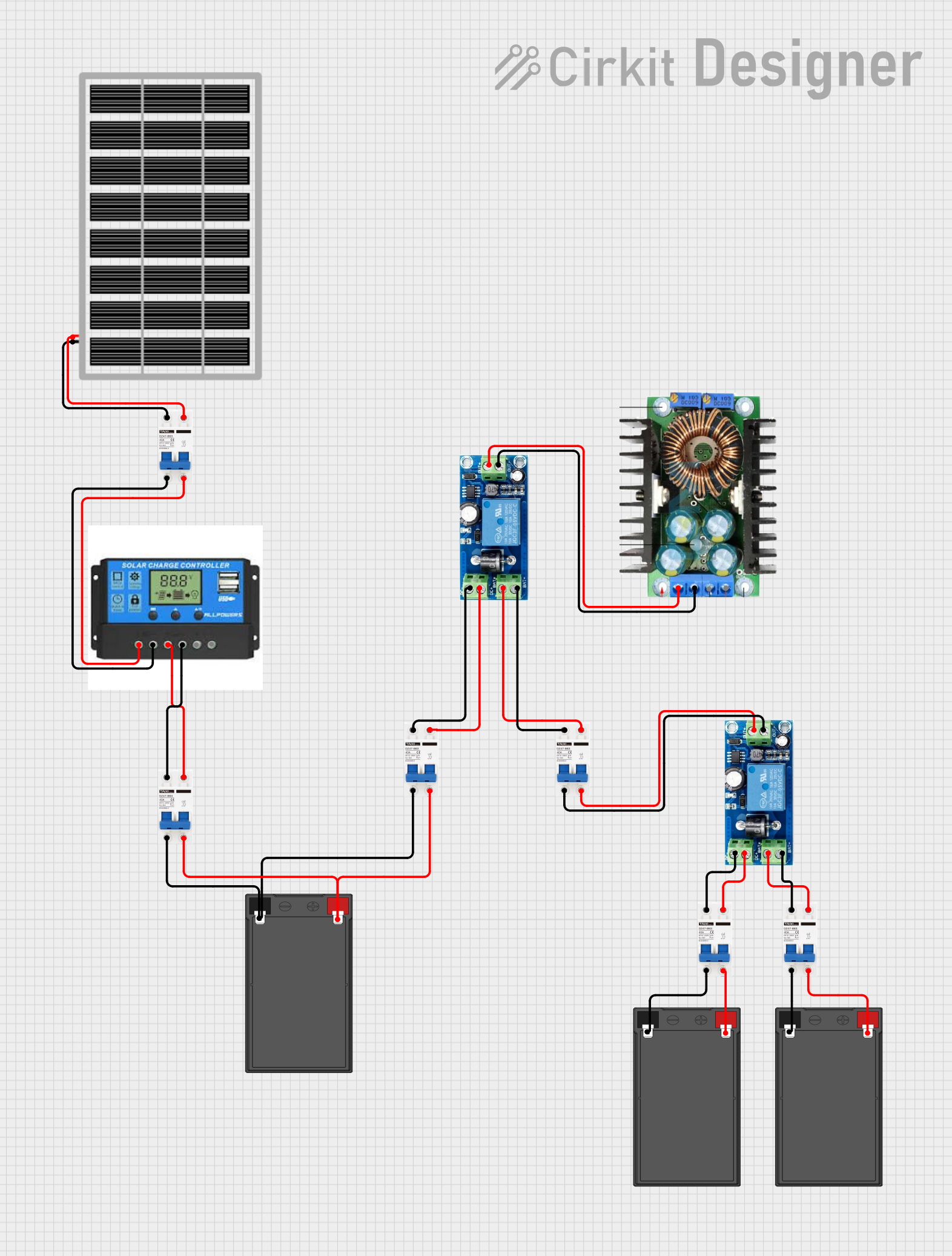
This circuit is designed to integrate a solar power system with multiple 12V batteries and a UPS module for uninterrupted power supply. The solar panel charges the batteries through a charge controller, which is protected by DC MCBs. The UPS modules are connected to the batteries and provide a regulated DC output, which is then adjusted by an XL4016 DC-DC converter module.
Battery-Powered 18650 Li-ion Charger with USB Output and Adjustable Voltage Regulator

This circuit is a battery management and power supply system that uses three 3.7V batteries connected to a 3S 10A Li-ion 18650 Charger Protection Board Module for balanced charging and protection. The system includes a TP4056 Battery Charging Protection Module for additional charging safety, a Step Up Boost Power Converter to regulate and boost the voltage, and a USB regulator to provide a stable 5V output, controlled by a push switch.
Solar-Powered Battery Charging System with DC-DC Converter
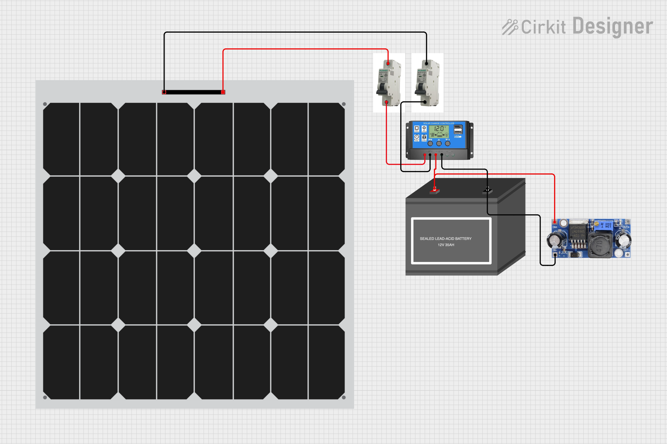
This circuit is a solar power system that uses two solar panels connected through MCBs to a solar charge controller. The charge controller manages the charging of a 12V battery and powers a DC-DC converter, which provides a regulated output voltage.
Explore Projects Built with MCB 3P
Solar-Powered Home Energy System with Automatic Transfer Switch and Battery Backup
This circuit is a solar power system with an automatic transfer switch (ATS) that manages power from both a solar panel and an AC supply. The solar panel charges a battery through a solar charge controller, and the power inverter converts the stored DC power to AC, which is then distributed through an MCB to a socket. The ATS ensures seamless switching between solar and AC power sources.
Solar-Powered UPS with Multiple Battery Management
This circuit is designed to integrate a solar power system with multiple 12V batteries and a UPS module for uninterrupted power supply. The solar panel charges the batteries through a charge controller, which is protected by DC MCBs. The UPS modules are connected to the batteries and provide a regulated DC output, which is then adjusted by an XL4016 DC-DC converter module.
Battery-Powered 18650 Li-ion Charger with USB Output and Adjustable Voltage Regulator
This circuit is a battery management and power supply system that uses three 3.7V batteries connected to a 3S 10A Li-ion 18650 Charger Protection Board Module for balanced charging and protection. The system includes a TP4056 Battery Charging Protection Module for additional charging safety, a Step Up Boost Power Converter to regulate and boost the voltage, and a USB regulator to provide a stable 5V output, controlled by a push switch.
Solar-Powered Battery Charging System with DC-DC Converter
This circuit is a solar power system that uses two solar panels connected through MCBs to a solar charge controller. The charge controller manages the charging of a 12V battery and powers a DC-DC converter, which provides a regulated output voltage.
Technical Specifications
- Type: Miniature Circuit Breaker (MCB), 3-pole
- Rated Voltage: 400V AC (typical for three-phase systems)
- Rated Current: 6A to 63A (varies by model)
- Breaking Capacity: 6kA to 10kA (depending on the model)
- Frequency: 50/60 Hz
- Trip Curve: B, C, or D (defines the tripping characteristics)
- Mounting: DIN rail (35mm standard)
- Operating Temperature: -5°C to +40°C
- Standards Compliance: IEC 60898-1, IEC 60947-2
Pin Configuration and Descriptions
The MCB 3P has three input terminals and three output terminals, corresponding to the three phases of the electrical system.
| Pin Number | Terminal Name | Description |
|---|---|---|
| 1 | L1 (Input) | Input terminal for phase 1 |
| 2 | L2 (Input) | Input terminal for phase 2 |
| 3 | L3 (Input) | Input terminal for phase 3 |
| 4 | L1 (Output) | Output terminal for phase 1 |
| 5 | L2 (Output) | Output terminal for phase 2 |
| 6 | L3 (Output) | Output terminal for phase 3 |
Usage Instructions
Installation:
- Ensure the power supply is turned off before installation.
- Mount the MCB 3P securely on a standard 35mm DIN rail.
- Connect the input terminals (L1, L2, L3) to the incoming three-phase power supply.
- Connect the output terminals (L1, L2, L3) to the load or downstream circuit.
- Tighten all terminal screws to ensure a secure connection.
Operation:
- Switch the MCB to the "ON" position to allow current flow through the circuit.
- In the event of an overload or short circuit, the MCB will automatically trip to the "OFF" position, disconnecting the circuit.
Resetting:
- After resolving the fault, switch the MCB back to the "ON" position to restore power.
Important Considerations:
- Select an MCB with the appropriate current rating and trip curve for your application.
- Avoid exceeding the rated voltage or current of the MCB.
- Regularly inspect the MCB for signs of wear or damage.
Best Practices:
- Use proper wire sizes to match the current rating of the MCB.
- Label the MCB to indicate the circuit it protects for easy identification.
- Test the MCB periodically to ensure it trips correctly under fault conditions.
Troubleshooting and FAQs
Common Issues
MCB trips frequently:
- Cause: Overloaded circuit or short circuit.
- Solution: Reduce the load on the circuit or check for wiring faults.
MCB does not trip during a fault:
- Cause: Faulty MCB or incorrect current rating.
- Solution: Replace the MCB with a properly rated and functioning unit.
MCB cannot be switched back to "ON":
- Cause: Persistent fault in the circuit.
- Solution: Identify and resolve the fault before resetting the MCB.
FAQs
Can I use an MCB 3P for single-phase systems?
- Yes, but only one pole will be used, which is not an efficient use of the device. It is recommended to use a single-pole MCB for single-phase systems.
What is the difference between trip curves B, C, and D?
- B Curve: Trips at 3-5 times the rated current, suitable for resistive loads.
- C Curve: Trips at 5-10 times the rated current, ideal for inductive loads like motors.
- D Curve: Trips at 10-20 times the rated current, used for high inrush current loads.
How do I select the correct MCB for my application?
- Determine the load current, type of load (resistive or inductive), and the fault current level. Choose an MCB with the appropriate current rating, trip curve, and breaking capacity.
By following this documentation, users can safely and effectively install and operate the MCB 3P in their electrical systems.