How to Use traffic light : Examples, Pinouts, and Specs
Introduction
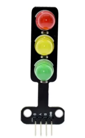
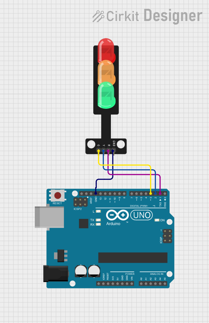
A traffic light module is an electronic component that simulates the operation of standard traffic lights. It typically consists of a set of LEDs (red, yellow, and green) that can be controlled to replicate the sequence of a traffic signal. This module is commonly used in educational settings to teach the basics of electronic circuit design and control logic, as well as in hobbyist projects for creating traffic light systems for model roadways.
Explore Projects Built with traffic light
Explore Projects Built with traffic light
Common Applications and Use Cases
- Educational projects to demonstrate traffic control systems
- Model traffic light systems for model railroads or roadways
- Interactive exhibits for museums or science centers
- Prototyping traffic management solutions
Technical Specifications
Key Technical Details
- Operating Voltage: Typically 3.3V to 5V
- Current Consumption: Varies with LED color and intensity, typically 10-20 mA per LED
- Power Ratings: Dependent on LED specifications, usually around 60-100 mW per LED
Pin Configuration and Descriptions
| Pin Number | Description | Notes |
|---|---|---|
| 1 | Red LED control | Active HIGH or LOW depending on module design |
| 2 | Yellow LED control | Active HIGH or LOW depending on module design |
| 3 | Green LED control | Active HIGH or LOW depending on module design |
| 4 | Ground (GND) | Common ground for all LEDs |
| 5 | VCC | Supply voltage for the module |
Usage Instructions
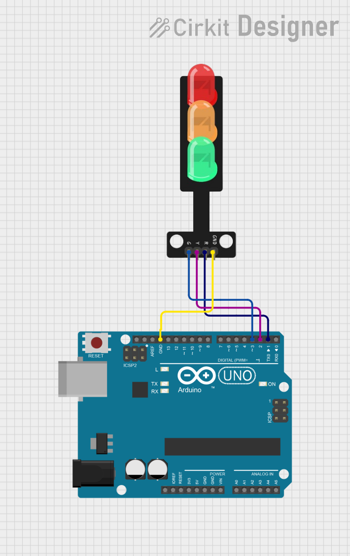
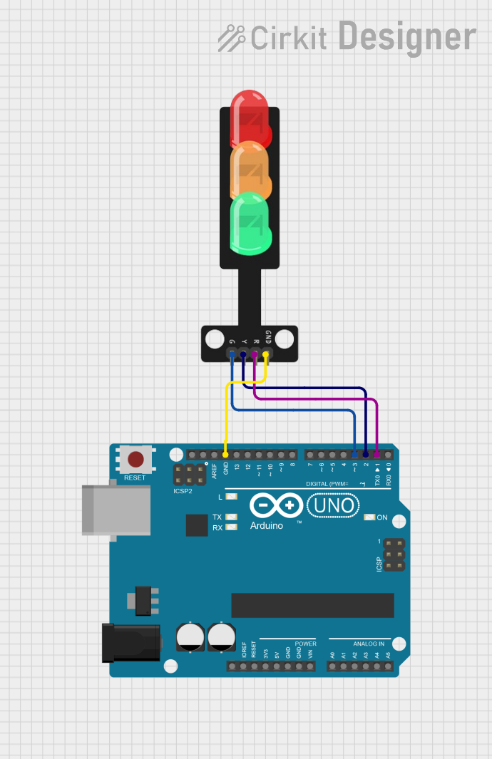
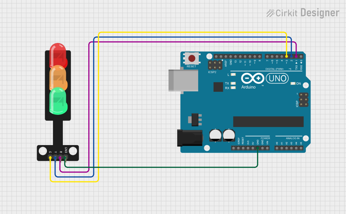
How to Use the Component in a Circuit
- Connect the VCC pin to the positive supply voltage (3.3V or 5V).
- Connect the GND pin to the ground of the power supply.
- Interface the control pins (Red, Yellow, Green) to the output pins of a microcontroller or switch.
- Use a current-limiting resistor if not built into the module to prevent LED damage.
Important Considerations and Best Practices
- Ensure that the supply voltage matches the module's requirements.
- Use current-limiting resistors if the module does not have built-in resistors.
- Avoid connecting the LEDs directly to a high current source.
- Use pulse-width modulation (PWM) for dimming the LEDs if required.
Example Code for Arduino UNO
// Define the control pins for the traffic light LEDs
const int redLED = 2;
const int yellowLED = 3;
const int greenLED = 4;

void setup() {
  // Set the LED pins as outputs
  pinMode(redLED, OUTPUT);
  pinMode(yellowLED, OUTPUT);
  pinMode(greenLED, OUTPUT);
}

void loop() {
  // Red light for 5 seconds
  digitalWrite(redLED, HIGH);
  delay(5000);
  digitalWrite(redLED, LOW);

  // Green light for 5 seconds
  digitalWrite(greenLED, HIGH);
  delay(5000);
  digitalWrite(greenLED, LOW);

  // Yellow light for 2 seconds
  digitalWrite(yellowLED, HIGH);
  delay(2000);
  digitalWrite(yellowLED, LOW);

  // Repeat the cycle
}
Troubleshooting and FAQs
Common Issues Users Might Face
- LEDs not lighting up: Check the power supply connections and ensure that the control pins are correctly connected to the microcontroller.
- LEDs too dim or too bright: Verify that the correct current-limiting resistors are used. Adjust the PWM values if dimming is required.
- One or more LEDs not functioning: Ensure that there are no loose connections and that the LEDs are not damaged.
Solutions and Tips for Troubleshooting
- Double-check wiring against the pin configuration table.
- Use a multimeter to verify the voltage at the LED pins.
- Replace the LEDs if they are found to be faulty.
- Ensure that the microcontroller's code is uploaded correctly and functioning as intended.
FAQs
Q: Can I use a different voltage supply for the traffic light module? A: It is essential to use a voltage supply that matches the module's specifications to prevent damage to the LEDs.
Q: How can I make the traffic light sequence more realistic? A: Implement a state machine in your microcontroller code to more accurately represent the timing and sequence of a real traffic light.
Q: Can I control the brightness of the LEDs? A: Yes, you can use PWM on the control pins to adjust the brightness of the LEDs.