How to Use Telemetry Radio: Examples, Pinouts, and Specs
Introduction
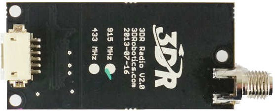
The SiK Telemetry Radio V3 by Holybro is a versatile and reliable device designed to transmit data from remote or inaccessible locations to a receiving station for monitoring and analysis. This telemetry radio is widely used in various applications, including unmanned aerial vehicles (UAVs), remote sensing, and other wireless communication systems. It provides a robust and efficient means of data transmission, ensuring that critical information is relayed accurately and promptly.
Explore Projects Built with Telemetry Radio

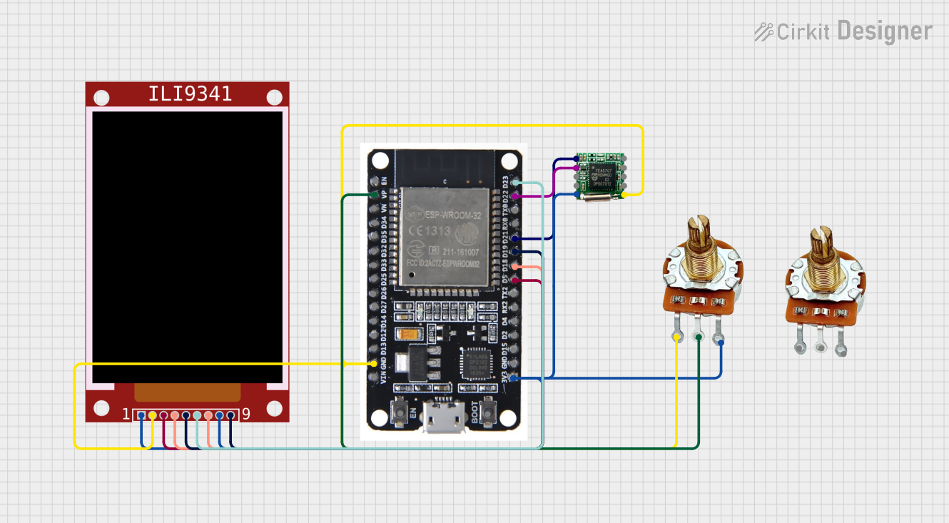
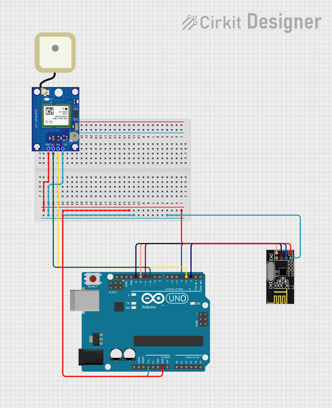

Explore Projects Built with Telemetry Radio
Technical Specifications
Key Technical Details
| Parameter | Value |
|---|---|
| Frequency Range | 433 MHz / 915 MHz |
| Transmit Power | Up to 100 mW (20 dBm) |
| Sensitivity | -121 dBm |
| Data Rate | Up to 250 kbps |
| Voltage Range | 3.3V - 5.5V |
| Current Consumption | 100 mA (typical) |
| Interface | UART |
| Antenna Connector | RP-SMA |
| Dimensions | 25mm x 55mm x 12mm |
| Weight | 12 grams |
Pin Configuration and Descriptions
| Pin Number | Pin Name | Description |
|---|---|---|
| 1 | VCC | Power supply (3.3V - 5.5V) |
| 2 | GND | Ground |
| 3 | TX | UART Transmit |
| 4 | RX | UART Receive |
| 5 | CTS | Clear to Send (Flow Control) |
| 6 | RTS | Request to Send (Flow Control) |
| 7 | LED1 | Status LED 1 |
| 8 | LED2 | Status LED 2 |
Usage Instructions
How to Use the SiK Telemetry Radio V3 in a Circuit
- Power Supply: Connect the VCC pin to a 3.3V - 5.5V power source and the GND pin to the ground of your circuit.
- UART Connection: Connect the TX pin of the telemetry radio to the RX pin of your microcontroller (e.g., Arduino UNO) and the RX pin of the telemetry radio to the TX pin of your microcontroller.
- Flow Control (Optional): If you are using flow control, connect the CTS and RTS pins to the corresponding pins on your microcontroller.
- Antenna: Attach an appropriate antenna to the RP-SMA connector to ensure optimal signal transmission and reception.
Important Considerations and Best Practices
- Antenna Placement: Ensure that the antenna is placed in a location free from obstructions and interference to maximize signal strength and range.
- Power Supply: Use a stable power supply within the specified voltage range to avoid damaging the telemetry radio.
- Baud Rate: Configure the UART baud rate to match the settings of your microcontroller and other communication devices.
- Firmware Updates: Periodically check for firmware updates from Holybro to ensure your telemetry radio is running the latest software.
Example Code for Arduino UNO
#include <SoftwareSerial.h>

// Define the pins for the telemetry radio
const int TX_PIN = 2;
const int RX_PIN = 3;

// Create a SoftwareSerial object
SoftwareSerial telemetrySerial(TX_PIN, RX_PIN);

void setup() {
  // Start the hardware serial for debugging
  Serial.begin(9600);

  // Start the software serial for telemetry communication
  telemetrySerial.begin(57600); // Ensure this matches the telemetry radio's baud rate

  Serial.println("Telemetry Radio Initialized");
}

void loop() {
  // Check if data is available from the telemetry radio
  if (telemetrySerial.available()) {
    // Read the data and print it to the hardware serial
    char incomingData = telemetrySerial.read();
    Serial.print(incomingData);
  }

  // Check if data is available from the hardware serial
  if (Serial.available()) {
    // Read the data and send it to the telemetry radio
    char outgoingData = Serial.read();
    telemetrySerial.print(outgoingData);
  }
}
Troubleshooting and FAQs
Common Issues and Solutions
No Data Transmission
- Solution: Ensure that the TX and RX pins are correctly connected. Verify that the baud rate settings match between the telemetry radio and the microcontroller.
Weak Signal or Interference
- Solution: Check the antenna placement and ensure it is free from obstructions. Consider using a higher gain antenna if necessary.
Power Issues
- Solution: Verify that the power supply voltage is within the specified range (3.3V - 5.5V). Ensure that the power source can supply sufficient current (at least 100 mA).
Firmware Compatibility
- Solution: Ensure that both the transmitter and receiver telemetry radios are running compatible firmware versions. Update the firmware if necessary.
FAQs
Q1: Can I use the SiK Telemetry Radio V3 with other microcontrollers besides Arduino?
- A1: Yes, the SiK Telemetry Radio V3 can be used with any microcontroller that supports UART communication.
Q2: What is the maximum range of the SiK Telemetry Radio V3?
- A2: The maximum range depends on various factors, including antenna type, placement, and environmental conditions. Under optimal conditions, it can achieve ranges of several kilometers.
Q3: How do I update the firmware on the SiK Telemetry Radio V3?
- A3: Firmware updates can be performed using the Mission Planner software or other compatible ground control software. Follow the instructions provided by Holybro for detailed steps.
Q4: Is it necessary to use flow control (CTS/RTS) with the SiK Telemetry Radio V3?
- A4: Flow control is optional but recommended for reliable data transmission, especially at higher data rates.
By following this documentation, users can effectively integrate and utilize the SiK Telemetry Radio V3 in their projects, ensuring reliable and efficient data transmission.