Cirkit Designer
Your all-in-one circuit design IDE
Home /
Component Documentation
How to Use Display Module: Examples, Pinouts, and Specs
Adafruit TFT-ST7789 Display Module Documentation
1. Introduction
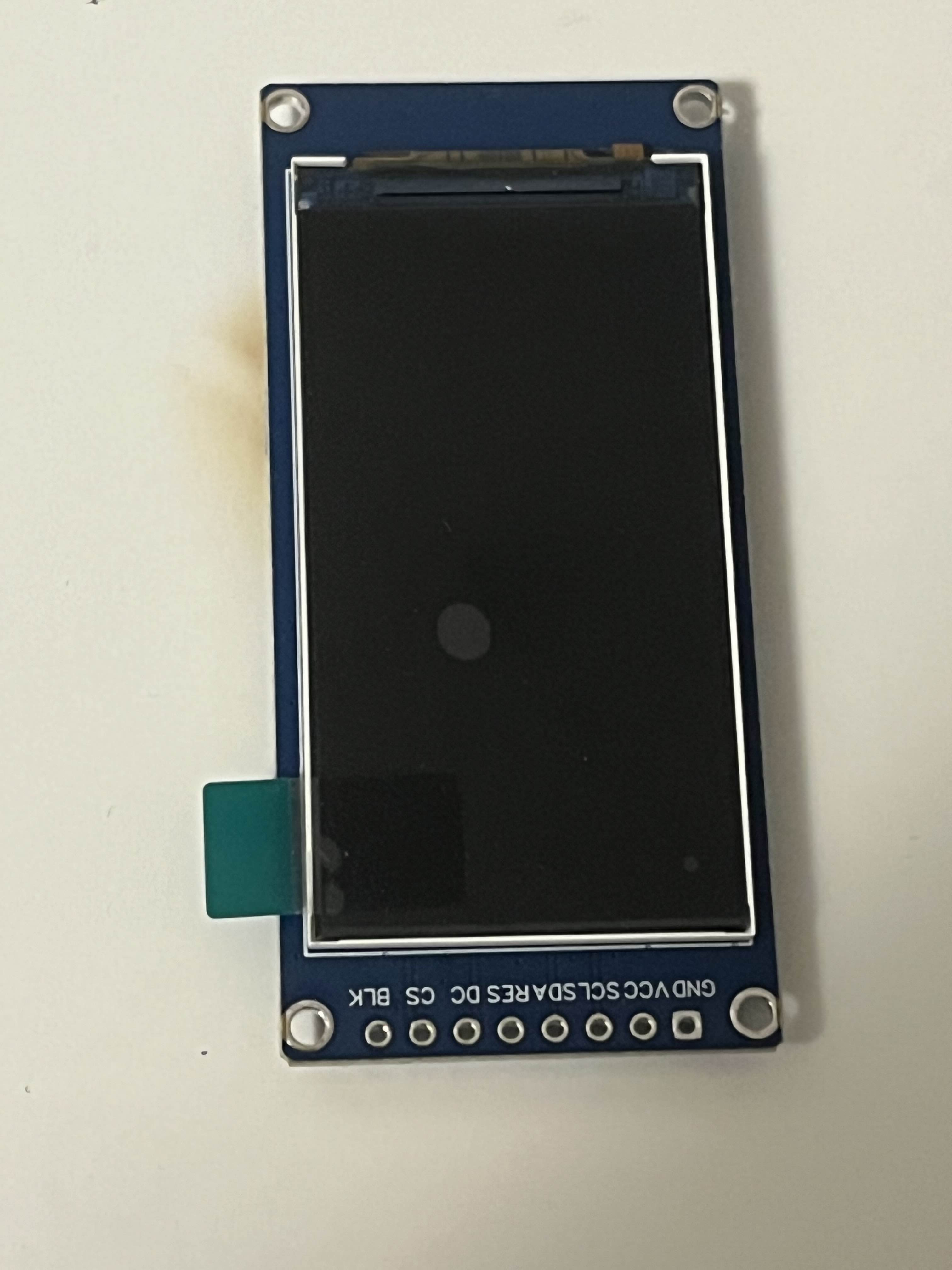
The Adafruit TFT-ST7789 Display Module is a versatile electronic component designed to visually present information, including text, images, and video. This display module leverages TFT (Thin-Film Transistor) technology, providing vibrant colors and high-resolution graphics. It is commonly used in various applications such as embedded systems, portable devices, and DIY electronics projects.
Common Applications and Use Cases
- Embedded Systems: Displaying system status, user interfaces, and real-time data.
- Portable Devices: Screens for handheld gadgets, wearables, and portable gaming consoles.
- DIY Electronics Projects: Visual output for Arduino, Raspberry Pi, and other microcontroller projects.
- Industrial Control Panels: Displaying operational data and control interfaces.
2. Technical Specifications
Key Technical Details
| Specification | Value |
|---|---|
| Display Type | TFT |
| Controller | ST7789 |
| Screen Size | 1.3 inches |
| Resolution | 240 x 240 pixels |
| Interface | SPI |
| Operating Voltage | 3.3V |
| Operating Current | 40mA (typical) |
| Backlight | LED |
| Viewing Angle | 160 degrees |
| Operating Temperature | -20°C to 70°C |
Pin Configuration and Descriptions
| Pin Number | Pin Name | Description |
|---|---|---|
| 1 | VCC | Power supply (3.3V) |
| 2 | GND | Ground |
| 3 | SCL | Serial Clock Line (SPI) |
| 4 | SDA | Serial Data Line (SPI) |
| 5 | RES | Reset |
| 6 | DC | Data/Command Control |
| 7 | CS | Chip Select |
| 8 | BLK | Backlight Control (optional, can be tied to VCC) |
3. Usage Instructions
How to Use the Component in a Circuit
Power Supply:
- Connect the VCC pin to a 3.3V power source.
- Connect the GND pin to the ground of your circuit.
SPI Interface:
- Connect the SCL pin to the SPI clock pin of your microcontroller.
- Connect the SDA pin to the SPI data pin of your microcontroller.
- Connect the CS pin to a digital pin on your microcontroller to act as the chip select.
Control Pins:
- Connect the RES pin to a digital pin on your microcontroller for resetting the display.
- Connect the DC pin to a digital pin on your microcontroller to switch between data and command mode.
Backlight:
- Optionally, connect the BLK pin to a PWM-capable pin on your microcontroller to control the backlight brightness. Alternatively, tie it to VCC for full brightness.
Important Considerations and Best Practices
- Voltage Levels: Ensure that the voltage levels are compatible with the display module. The module operates at 3.3V, so use level shifters if interfacing with a 5V system.
- Initialization Sequence: Follow the correct initialization sequence as specified in the ST7789 datasheet to ensure proper operation.
- ESD Precautions: Handle the display module with care to avoid electrostatic discharge (ESD) damage.
Example Code for Arduino UNO
#include <Adafruit_GFX.h>    // Core graphics library
#include <Adafruit_ST7789.h> // Hardware-specific library for ST7789

#define TFT_CS     10
#define TFT_RST    9
#define TFT_DC     8

// Initialize Adafruit ST7789 TFT library
Adafruit_ST7789 tft = Adafruit_ST7789(TFT_CS, TFT_DC, TFT_RST);

void setup() {
  // Initialize the display
  tft.init(240, 240); // Initialize with a resolution of 240x240 pixels
  tft.setRotation(1); // Set display rotation

  // Fill the screen with black color
  tft.fillScreen(ST77XX_BLACK);

  // Display a message
  tft.setCursor(10, 10);
  tft.setTextColor(ST77XX_WHITE);
  tft.setTextSize(2);
  tft.println("Hello, World!");
}

void loop() {
  // Add your main code here, to run repeatedly
}
4. Troubleshooting and FAQs
Common Issues Users Might Face
Display Not Turning On:
- Solution: Check the power connections and ensure that the VCC and GND pins are properly connected.
No Display Output:
- Solution: Verify the SPI connections and ensure that the CS, SCL, and SDA pins are correctly connected to the microcontroller.
Flickering or Unstable Display:
- Solution: Ensure that the power supply is stable and that the backlight control (BLK) is properly connected.
Incorrect Colors or Graphics:
- Solution: Check the initialization sequence and ensure that the display settings (e.g., rotation, color mode) are correctly configured in the code.
Solutions and Tips for Troubleshooting
- Double-Check Connections: Ensure all connections are secure and correctly mapped according to the pin configuration table.
- Use a Multimeter: Measure the voltage levels at the VCC and GND pins to ensure proper power supply.
- Consult the Datasheet: Refer to the ST7789 datasheet for detailed information on initialization and control commands.
- Update Libraries: Ensure that you are using the latest versions of the Adafruit GFX and Adafruit ST7789 libraries.
By following this documentation, users can effectively integrate and utilize the Adafruit TFT-ST7789 Display Module in their projects, ensuring optimal performance and reliability.
Explore Projects Built with Display Module
DC-DC Converter and Relay Module Power Distribution System

This circuit consists of a DC-DC converter powering a 6-channel power module, which in turn supplies 5V to a 2-relay module. The power module distributes the converted voltage to the relay module, enabling it to control external devices.
ESP8266 NodeMCU-Based Environmental Monitoring System with SIM900A GSM Communication

This is a sensor-based data acquisition system with GSM communication capability. It uses an ESP8266 NodeMCU to collect environmental data from a DHT22 sensor and light levels from an LDR, as well as distance measurements from an HC-SR04 ultrasonic sensor. The SIM900A GSM module enables the system to transmit the collected data over a cellular network.
ESP32-S3 Battery-Powered Environmental Monitoring System with OLED Display

This circuit is a sensor and display system powered by a UPS module with a 12V power supply and 18650 batteries. It includes an ESP32 microcontroller that interfaces with various sensors (DHT22, Strain Gauge, MPU-6050, ADXL345) and an OLED display, with power regulation provided by a step-down buck converter.
Arduino UNO Controlled RGB LED Matrix with Bluetooth Connectivity and Audio Output

This is an interactive display and communication circuit. It uses an Arduino UNO to drive multiple WS2812 RGB LED matrices for visual output, interfaces with a DS3231 RTC for time-related functions, and communicates wirelessly via an HC-05 Bluetooth module. Additionally, it features audio output capabilities through a speaker connected to a PAM8403 audio amplifier.
Explore Projects Built with Display Module
DC-DC Converter and Relay Module Power Distribution System
This circuit consists of a DC-DC converter powering a 6-channel power module, which in turn supplies 5V to a 2-relay module. The power module distributes the converted voltage to the relay module, enabling it to control external devices.
ESP8266 NodeMCU-Based Environmental Monitoring System with SIM900A GSM Communication
This is a sensor-based data acquisition system with GSM communication capability. It uses an ESP8266 NodeMCU to collect environmental data from a DHT22 sensor and light levels from an LDR, as well as distance measurements from an HC-SR04 ultrasonic sensor. The SIM900A GSM module enables the system to transmit the collected data over a cellular network.
ESP32-S3 Battery-Powered Environmental Monitoring System with OLED Display
This circuit is a sensor and display system powered by a UPS module with a 12V power supply and 18650 batteries. It includes an ESP32 microcontroller that interfaces with various sensors (DHT22, Strain Gauge, MPU-6050, ADXL345) and an OLED display, with power regulation provided by a step-down buck converter.
Arduino UNO Controlled RGB LED Matrix with Bluetooth Connectivity and Audio Output
This is an interactive display and communication circuit. It uses an Arduino UNO to drive multiple WS2812 RGB LED matrices for visual output, interfaces with a DS3231 RTC for time-related functions, and communicates wirelessly via an HC-05 Bluetooth module. Additionally, it features audio output capabilities through a speaker connected to a PAM8403 audio amplifier.