How to Use Throttle: Examples, Pinouts, and Specs
Introduction
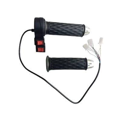
A throttle is a device used to regulate the flow of fuel or air into an engine, thereby controlling its power output and speed. It is a critical component in internal combustion engines, commonly found in automobiles, motorcycles, and other machinery. By adjusting the throttle, users can control the engine's performance, from idling to full power.
Explore Projects Built with Throttle
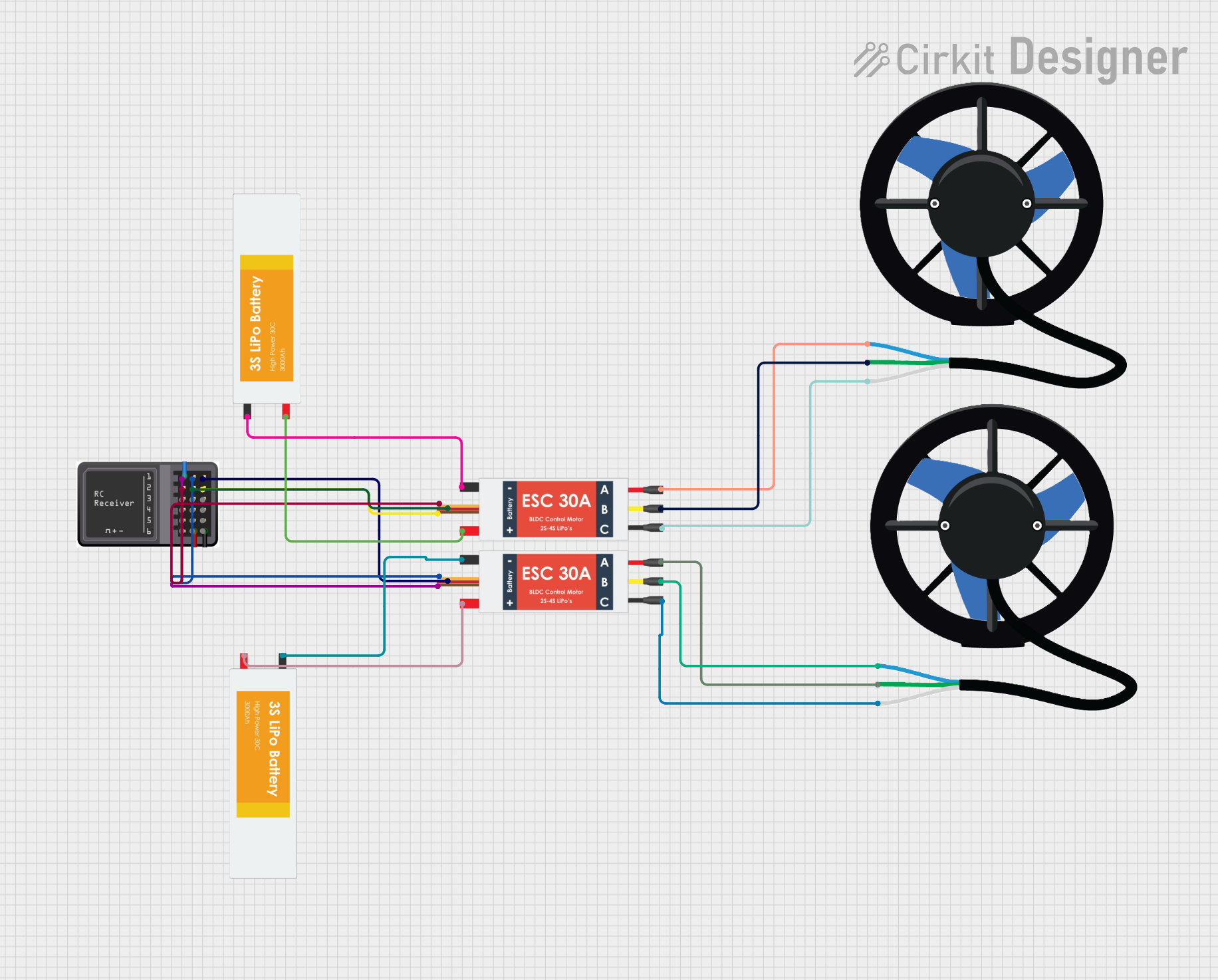
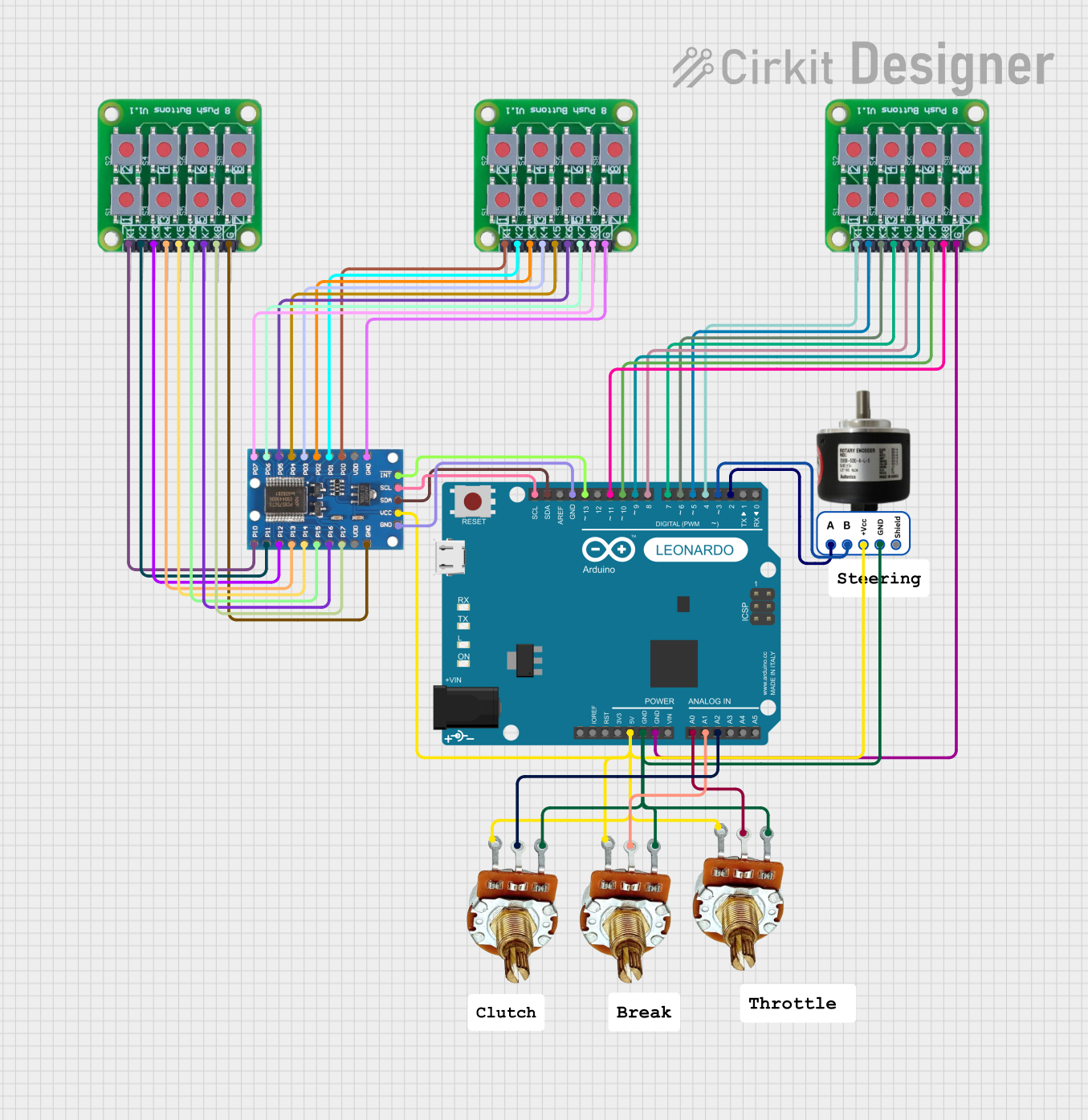
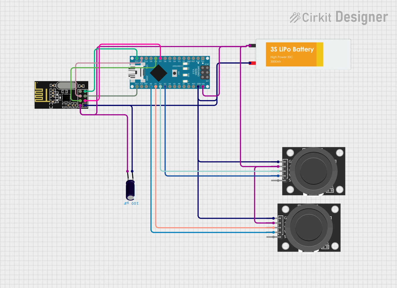
Explore Projects Built with Throttle
Common Applications and Use Cases
- Automotive engines for speed and power control
- Motorcycles and scooters for acceleration management
- Industrial machinery with internal combustion engines
- Generators and other power equipment
- Aircraft engines for precise power adjustments
Technical Specifications
The technical specifications of a throttle can vary depending on its type (mechanical, electronic, or drive-by-wire). Below are general specifications for an electronic throttle control (ETC) system:
| Parameter | Specification |
|---|---|
| Operating Voltage | 5V DC (typical for sensors) |
| Signal Output Type | Analog (0.5V to 4.5V) |
| Operating Temperature | -40°C to 125°C |
| Throttle Position Sensor | Dual potentiometer or Hall effect |
| Connector Type | 3-pin or 6-pin (depending on design) |
| Response Time | <10 ms |
Pin Configuration and Descriptions
Below is a typical pinout for an electronic throttle position sensor (TPS):
| Pin | Name | Description |
|---|---|---|
| 1 | VCC | Power supply input (typically 5V) |
| 2 | GND | Ground connection |
| 3 | Signal Output 1 | Analog signal proportional to throttle position |
| 4 | Signal Output 2 | Redundant analog signal for safety (optional) |
| 5 | CAN_H (optional) | High line for CAN bus communication (if applicable) |
| 6 | CAN_L (optional) | Low line for CAN bus communication (if applicable) |
Usage Instructions
How to Use the Throttle in a Circuit
- Power the Throttle Sensor: Connect the VCC pin to a 5V DC power source and the GND pin to the ground.
- Read the Signal Output: Use an analog-to-digital converter (ADC) to read the signal output from the throttle position sensor. The voltage will vary between 0.5V (closed throttle) and 4.5V (fully open throttle).
- Optional Redundant Signal: If the sensor provides a second signal output, use it for redundancy or safety checks.
- Communication (if applicable): For advanced systems, connect the CAN_H and CAN_L pins to a CAN bus for digital communication.
Important Considerations and Best Practices
- Calibration: Ensure the throttle position sensor is calibrated to match the engine's requirements.
- Safety: For electronic throttle control systems, always implement fail-safe mechanisms to handle sensor failures.
- Wiring: Use shielded cables to minimize noise interference, especially in automotive environments.
- Testing: Verify the throttle's response time and accuracy before integrating it into the system.
Example: Connecting a Throttle to an Arduino UNO
Below is an example of how to read the throttle position sensor's output using an Arduino UNO:
// Throttle Position Sensor Example with Arduino UNO
// Reads the analog signal from the throttle and prints the position to Serial Monitor

const int throttlePin = A0; // Connect the signal output of the throttle to A0
int throttleValue = 0;      // Variable to store the throttle position value

void setup() {
  Serial.begin(9600); // Initialize serial communication at 9600 baud
  pinMode(throttlePin, INPUT); // Set the throttle pin as input
}

void loop() {
  // Read the analog value from the throttle (0-1023)
  throttleValue = analogRead(throttlePin);

  // Convert the value to a percentage (0% to 100%)
  float throttlePercentage = map(throttleValue, 0, 1023, 0, 100);

  // Print the throttle position to the Serial Monitor
  Serial.print("Throttle Position: ");
  Serial.print(throttlePercentage);
  Serial.println("%");

  delay(100); // Delay for stability
}
Troubleshooting and FAQs
Common Issues and Solutions
No Signal Output:
- Cause: Incorrect wiring or power supply issues.
- Solution: Verify the connections and ensure the VCC and GND pins are properly connected.
Inconsistent Readings:
- Cause: Electrical noise or a faulty sensor.
- Solution: Use shielded cables and check the sensor for damage.
Signal Stuck at Maximum or Minimum:
- Cause: Sensor failure or mechanical blockage in the throttle body.
- Solution: Inspect the sensor and throttle body for obstructions or damage.
Slow Response Time:
- Cause: Faulty wiring or a lagging ADC.
- Solution: Check the wiring and ensure the ADC is functioning correctly.
FAQs
Q: Can I use a throttle sensor with a 3.3V microcontroller?
A: Yes, but you may need a voltage divider or level shifter to ensure compatibility with the sensor's 5V output.
Q: How do I calibrate a throttle position sensor?
A: Calibration typically involves setting the closed and fully open throttle positions in the engine control unit (ECU) or microcontroller.
Q: What happens if the throttle sensor fails?
A: In most systems, the ECU will enter a fail-safe mode, limiting engine power to prevent unsafe operation.
Q: Can I use a throttle sensor for non-automotive applications?
A: Yes, throttle sensors can be used in any application requiring precise position or flow control, such as robotics or industrial machinery.