Cirkit Designer Logo
Cirkit Designer
Your all-in-one circuit design IDE
Home / 
Component Documentation

How to Use Fluxgate: Examples, Pinouts, and Specs

Image of Fluxgate
Cirkit Designer LogoDesign with Fluxgate in Cirkit Designer

Introduction

A fluxgate is a type of magnetic sensor used to measure the strength and direction of magnetic fields. It operates by utilizing a core material that becomes magnetized in response to an external magnetic field. This property allows for precise and reliable measurements, making fluxgate sensors ideal for applications such as navigation, geophysical surveys, and industrial monitoring. Their high sensitivity and ability to detect weak magnetic fields make them indispensable in scientific research and aerospace systems.

Explore Projects Built with Fluxgate

Use Cirkit Designer to design, explore, and prototype these projects online. Some projects support real-time simulation. Click "Open Project" to start designing instantly!
Satellite-Based Timing and Navigation System with SDR and Atomic Clock Synchronization
Image of GPS 시스템 측정 구성도_Confirm: A project utilizing Fluxgate in a practical application
This circuit appears to be a complex system involving power supply management, GPS and timing synchronization, and data communication. It includes a SI-TEX G1 Satellite Compass for GPS data, an XHTF1021 Atomic Rubidium Clock for precise timing, and Ettus USRP B200 units for software-defined radio communication. Power is supplied through various SMPS units and distributed via terminal blocks and DC jacks. Data communication is facilitated by Beelink MINI S12 N95 computers, RS232 splitters, and a 1000BASE-T Media Converter for network connectivity. RF Directional Couplers are used to interface antennas with the USRP units, and the entire system is likely contained within cases for protection and organization.
Cirkit Designer LogoOpen Project in Cirkit Designer
Arduino UNO-Based RFID and Ultrasonic Sensor Automated Toll Gate with LED Indicators and Buzzer
Image of tollgate: A project utilizing Fluxgate in a practical application
This circuit is an automated toll gate system using an Arduino UNO, which controls a servo motor to open and close the gate based on RFID tag detection and ultrasonic sensor input. The system includes red and green LEDs for status indication, a buzzer for unauthorized access alerts, and a toggle switch for manual control.
Cirkit Designer LogoOpen Project in Cirkit Designer
ESP32 and Arduino Mega 2560 Controlled Peristaltic Pump System with Pressure and Flow Sensors
Image of Blood & Dialysate Control Bench: A project utilizing Fluxgate in a practical application
This circuit is designed for fluid control and monitoring, featuring multiple peristaltic pumps driven by TB6600 micro-stepping motor drivers, and pressure sensors interfaced with custom PCBs containing ESP32 microcontrollers. It also includes flow meters connected to Arduino Mega 2560 boards for precise flow rate measurement, with power management handled by DC-DC converters and power supplies.
Cirkit Designer LogoOpen Project in Cirkit Designer
Capacitive Force Sensor Data Acquisition System with Flex Resistors
Image of Thin Force Sensors: A project utilizing Fluxgate in a practical application
This circuit is designed to interface multiple capacitive force sensors and flex resistors with a Data Acquisition (DAQ) system. The sensors and resistors are connected through various resistors and capacitors to the DAQ, which collects and processes the sensor data. A Female BNC connector is also included for external signal input or output.
Cirkit Designer LogoOpen Project in Cirkit Designer

Explore Projects Built with Fluxgate

Use Cirkit Designer to design, explore, and prototype these projects online. Some projects support real-time simulation. Click "Open Project" to start designing instantly!
Image of GPS 시스템 측정 구성도_Confirm: A project utilizing Fluxgate in a practical application
Satellite-Based Timing and Navigation System with SDR and Atomic Clock Synchronization
This circuit appears to be a complex system involving power supply management, GPS and timing synchronization, and data communication. It includes a SI-TEX G1 Satellite Compass for GPS data, an XHTF1021 Atomic Rubidium Clock for precise timing, and Ettus USRP B200 units for software-defined radio communication. Power is supplied through various SMPS units and distributed via terminal blocks and DC jacks. Data communication is facilitated by Beelink MINI S12 N95 computers, RS232 splitters, and a 1000BASE-T Media Converter for network connectivity. RF Directional Couplers are used to interface antennas with the USRP units, and the entire system is likely contained within cases for protection and organization.
Cirkit Designer LogoOpen Project in Cirkit Designer
Image of tollgate: A project utilizing Fluxgate in a practical application
Arduino UNO-Based RFID and Ultrasonic Sensor Automated Toll Gate with LED Indicators and Buzzer
This circuit is an automated toll gate system using an Arduino UNO, which controls a servo motor to open and close the gate based on RFID tag detection and ultrasonic sensor input. The system includes red and green LEDs for status indication, a buzzer for unauthorized access alerts, and a toggle switch for manual control.
Cirkit Designer LogoOpen Project in Cirkit Designer
Image of Blood & Dialysate Control Bench: A project utilizing Fluxgate in a practical application
ESP32 and Arduino Mega 2560 Controlled Peristaltic Pump System with Pressure and Flow Sensors
This circuit is designed for fluid control and monitoring, featuring multiple peristaltic pumps driven by TB6600 micro-stepping motor drivers, and pressure sensors interfaced with custom PCBs containing ESP32 microcontrollers. It also includes flow meters connected to Arduino Mega 2560 boards for precise flow rate measurement, with power management handled by DC-DC converters and power supplies.
Cirkit Designer LogoOpen Project in Cirkit Designer
Image of Thin Force Sensors: A project utilizing Fluxgate in a practical application
Capacitive Force Sensor Data Acquisition System with Flex Resistors
This circuit is designed to interface multiple capacitive force sensors and flex resistors with a Data Acquisition (DAQ) system. The sensors and resistors are connected through various resistors and capacitors to the DAQ, which collects and processes the sensor data. A Female BNC connector is also included for external signal input or output.
Cirkit Designer LogoOpen Project in Cirkit Designer

Technical Specifications

Below are the key technical details and pin configuration for a typical fluxgate sensor:

Key Technical Details

  • Operating Voltage: 5V to 12V DC (varies by model)
  • Current Consumption: 10mA to 50mA
  • Measurement Range: ±100 µT to ±1 mT (microteslas to milliteslas)
  • Resolution: 0.1 µT or better
  • Frequency Response: DC to 1 kHz
  • Output Signal: Analog voltage or digital signal (depending on the model)
  • Operating Temperature: -40°C to +85°C
  • Core Material: High-permeability ferromagnetic alloy
  • Dimensions: Typically compact, e.g., 20mm x 20mm x 10mm (varies by model)

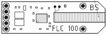
Pin Configuration and Descriptions

The pin configuration of a fluxgate sensor may vary depending on the manufacturer, but a common configuration is as follows:

Pin Number Pin Name Description
1 VCC Power supply input (5V to 12V DC).
2 GND Ground connection.
3 Signal Output Analog or digital output representing the measured magnetic field strength.
4 Enable/Control Optional pin to enable or disable the sensor (not present on all models).

Usage Instructions

How to Use the Fluxgate in a Circuit

  1. Power Supply: Connect the VCC pin to a stable DC power source (5V or 12V, depending on the sensor's specifications). Connect the GND pin to the ground of the power supply.
  2. Signal Output: Connect the Signal Output pin to an analog input pin of a microcontroller (e.g., Arduino) or to an oscilloscope for direct measurement.
  3. Enable/Control Pin: If the sensor has an Enable/Control pin, ensure it is connected to the appropriate logic level (e.g., HIGH to enable, LOW to disable).
  4. Magnetic Field Measurement: Place the fluxgate sensor in the environment where the magnetic field is to be measured. Ensure the sensor is oriented correctly to measure the desired field component (e.g., X, Y, or Z axis).

Important Considerations and Best Practices

  • Shielding: Avoid placing the fluxgate sensor near strong magnetic sources or ferromagnetic materials, as these can interfere with measurements.
  • Calibration: Periodically calibrate the sensor to ensure accurate readings, especially in environments with fluctuating magnetic fields.
  • Temperature Effects: Be mindful of the operating temperature range, as extreme temperatures can affect the sensor's performance.
  • Noise Filtering: Use appropriate filtering techniques (e.g., low-pass filters) to reduce noise in the output signal.

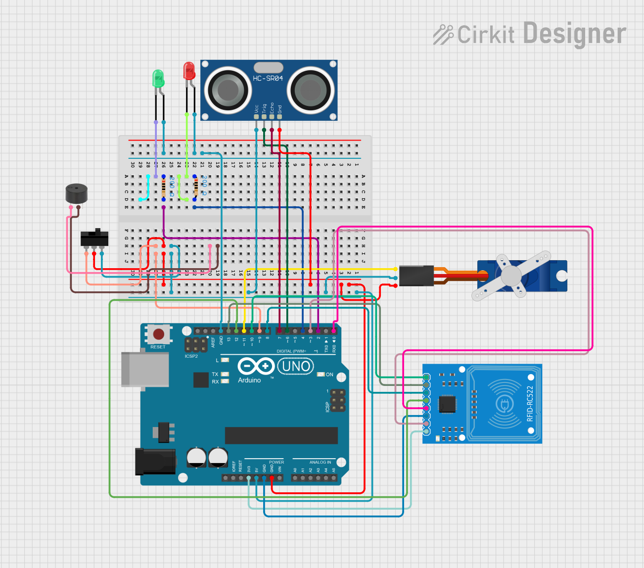
Example: Connecting a Fluxgate to an Arduino UNO

Below is an example of how to connect and read data from a fluxgate sensor using an Arduino UNO:

Circuit Diagram

  • Connect the VCC pin of the fluxgate to the 5V pin on the Arduino.
  • Connect the GND pin of the fluxgate to the GND pin on the Arduino.
  • Connect the Signal Output pin of the fluxgate to the A0 analog input pin on the Arduino.

Arduino Code

// Fluxgate Sensor Example with Arduino UNO
// Reads the analog output of the fluxgate sensor and prints the value to the Serial Monitor.

const int fluxgatePin = A0; // Analog pin connected to the fluxgate's Signal Output

void setup() {
  Serial.begin(9600); // Initialize serial communication at 9600 baud
  pinMode(fluxgatePin, INPUT); // Set the fluxgate pin as input
}

void loop() {
  int sensorValue = analogRead(fluxgatePin); // Read the analog value from the sensor
  float voltage = sensorValue * (5.0 / 1023.0); // Convert the reading to voltage
  
  // Print the voltage to the Serial Monitor
  Serial.print("Fluxgate Voltage: ");
  Serial.print(voltage);
  Serial.println(" V");
  
  delay(500); // Wait for 500ms before the next reading
}

Troubleshooting and FAQs

Common Issues and Solutions

  1. No Output Signal:

    • Cause: Incorrect wiring or insufficient power supply.
    • Solution: Double-check all connections and ensure the power supply meets the sensor's requirements.
  2. Inconsistent Readings:

    • Cause: External magnetic interference or improper sensor orientation.
    • Solution: Move the sensor away from magnetic sources and ensure it is properly aligned.
  3. High Noise in Output:

    • Cause: Electrical noise or lack of filtering.
    • Solution: Add a low-pass filter to the output signal or use shielded cables.
  4. Sensor Overheating:

    • Cause: Operating outside the specified voltage or temperature range.
    • Solution: Verify the power supply voltage and ensure the sensor is within the recommended temperature range.

FAQs

  • Q: Can the fluxgate sensor measure AC magnetic fields?

    • A: Yes, fluxgate sensors can measure AC magnetic fields, but their frequency response is typically limited to around 1 kHz.
  • Q: How do I calibrate a fluxgate sensor?

    • A: Calibration involves placing the sensor in a known magnetic field and adjusting the output to match the expected value. Refer to the manufacturer's guidelines for detailed calibration procedures.
  • Q: Can I use a fluxgate sensor underwater?

    • A: Only if the sensor is specifically designed for waterproof or underwater applications. Check the product specifications before use.
  • Q: What is the lifespan of a fluxgate sensor?

    • A: Fluxgate sensors are highly durable and can last for many years if used within their specified operating conditions.