Cirkit Designer Logo
Cirkit Designer
Your all-in-one circuit design IDE
Home / 
Component Documentation

How to Use Big Easy Driver ROB-11876: Examples, Pinouts, and Specs

Image of Big Easy Driver ROB-11876
Cirkit Designer LogoDesign with Big Easy Driver ROB-11876 in Cirkit Designer

Introduction

The Big Easy Driver (BED) ROB-11876 is a full-featured stepper motor driver board designed to control bipolar stepper motors. Based on the Allegro A4988 microstepping driver, the BED allows for fine control of stepper motors with an adjustable current output and seven different step resolutions. It is an ideal choice for applications requiring precise motion control such as 3D printers, CNC machines, and robotics.

Explore Projects Built with Big Easy Driver ROB-11876

Use Cirkit Designer to design, explore, and prototype these projects online. Some projects support real-time simulation. Click "Open Project" to start designing instantly!
Arduino UNO Controlled Linear Actuator and Stepper Motor System with Multiple Pushbuttons
Image of CircuitV2_2761_GBB: A project utilizing Big Easy Driver ROB-11876 in a practical application
This circuit features an Arduino-based control system with multiple pushbuttons and resistors for input, a relay module for switching, and a linear actuator and stepper motor for mechanical movement. The EasyDriver module interfaces the stepper motor with the Arduino, while the relay controls the linear actuator. Power is supplied via a 12V power supply and a DC barrel jack.
Cirkit Designer LogoOpen Project in Cirkit Designer
Battery-Powered Remote-Controlled Dual Motor System with Cytron URC10
Image of URC10 SUMO RC: A project utilizing Big Easy Driver ROB-11876 in a practical application
This circuit is a remote-controlled dual DC motor driver system powered by a 3S LiPo battery. It uses a Cytron URC10 motor driver to control two GM25 DC motors based on signals received from an R6FG receiver, with a rocker switch for power control and a 7-segment panel voltmeter for monitoring the battery voltage.
Cirkit Designer LogoOpen Project in Cirkit Designer
Battery-Powered Line Following Robot with IR Sensors and Cytron URC10 Motor Controller
Image of URC10 SUMO AUTO: A project utilizing Big Easy Driver ROB-11876 in a practical application
This circuit is a robotic control system that uses multiple IR sensors for line detection and obstacle avoidance, powered by a 3S LiPo battery. The Cytron URC10 motor driver, controlled by a microcontroller, drives two GM25 DC motors based on input from the sensors and a rocker switch, with a 7-segment panel voltmeter displaying the battery voltage.
Cirkit Designer LogoOpen Project in Cirkit Designer
Battery-Powered Line Following Robot with L298N Motor Driver and KY-033 Sensors
Image of obstacle-avoiding robot: A project utilizing Big Easy Driver ROB-11876 in a practical application
This circuit is designed to control a two-wheeled robot using an L298N motor driver, powered by two 18650 Li-ion batteries. It includes two KY-033 line tracking sensors for navigation and a 74HC04 inverter to process sensor signals and control the motor driver inputs.
Cirkit Designer LogoOpen Project in Cirkit Designer

Explore Projects Built with Big Easy Driver ROB-11876

Use Cirkit Designer to design, explore, and prototype these projects online. Some projects support real-time simulation. Click "Open Project" to start designing instantly!
Image of CircuitV2_2761_GBB: A project utilizing Big Easy Driver ROB-11876 in a practical application
Arduino UNO Controlled Linear Actuator and Stepper Motor System with Multiple Pushbuttons
This circuit features an Arduino-based control system with multiple pushbuttons and resistors for input, a relay module for switching, and a linear actuator and stepper motor for mechanical movement. The EasyDriver module interfaces the stepper motor with the Arduino, while the relay controls the linear actuator. Power is supplied via a 12V power supply and a DC barrel jack.
Cirkit Designer LogoOpen Project in Cirkit Designer
Image of URC10 SUMO RC: A project utilizing Big Easy Driver ROB-11876 in a practical application
Battery-Powered Remote-Controlled Dual Motor System with Cytron URC10
This circuit is a remote-controlled dual DC motor driver system powered by a 3S LiPo battery. It uses a Cytron URC10 motor driver to control two GM25 DC motors based on signals received from an R6FG receiver, with a rocker switch for power control and a 7-segment panel voltmeter for monitoring the battery voltage.
Cirkit Designer LogoOpen Project in Cirkit Designer
Image of URC10 SUMO AUTO: A project utilizing Big Easy Driver ROB-11876 in a practical application
Battery-Powered Line Following Robot with IR Sensors and Cytron URC10 Motor Controller
This circuit is a robotic control system that uses multiple IR sensors for line detection and obstacle avoidance, powered by a 3S LiPo battery. The Cytron URC10 motor driver, controlled by a microcontroller, drives two GM25 DC motors based on input from the sensors and a rocker switch, with a 7-segment panel voltmeter displaying the battery voltage.
Cirkit Designer LogoOpen Project in Cirkit Designer
Image of obstacle-avoiding robot: A project utilizing Big Easy Driver ROB-11876 in a practical application
Battery-Powered Line Following Robot with L298N Motor Driver and KY-033 Sensors
This circuit is designed to control a two-wheeled robot using an L298N motor driver, powered by two 18650 Li-ion batteries. It includes two KY-033 line tracking sensors for navigation and a 74HC04 inverter to process sensor signals and control the motor driver inputs.
Cirkit Designer LogoOpen Project in Cirkit Designer

Common Applications and Use Cases

  • 3D Printers
  • CNC Machines
  • Robotic Arms
  • Precision Positioning Systems
  • Automated Equipment

Technical Specifications

Key Technical Details

  • Maximum Current: 2A per phase (with sufficient additional cooling)
  • Voltage Range: 8V to 35V
  • Logic Input Voltage Range: 3V to 5.5V
  • Step Resolutions: Full, 1/2, 1/4, 1/8, 1/16, 1/32
  • Dimensions: 1.35in x 1.95in (34.3mm x 49.5mm)

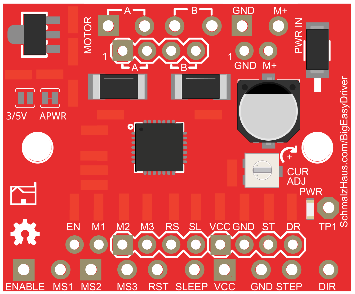
Pin Configuration and Descriptions

Pin Name Description
GND Ground connection
M+ Motor power supply (8V to 35V)
AOUT1/AOUT2 Motor coil A connections
BOUT1/BOUT2 Motor coil B connections
STEP Step input (pulses from the controller)
DIR Direction input (high for one direction, low for the other)
MS1, MS2, MS3 Microstep resolution select inputs
ENABLE Enables (low) or disables (high) the FET outputs
SLEEP Logic low puts the board into low power sleep mode
RESET Logic low resets the internal translator and disables all outputs
PFD Sets the percentage of fast decay in mixed decay mode
VDD Logic supply voltage (should be the same as the logic input voltage)
5VOUT Regulated 5V output (up to 50mA for powering logic circuitry)
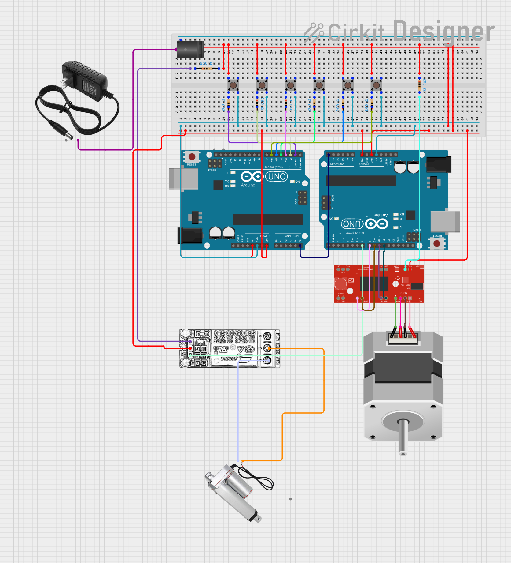
Usage Instructions

How to Use the Component in a Circuit

  1. Power Connections:

    • Connect the motor power supply to the M+ and GND pins.
    • Ensure that the power supply voltage is within the specified range (8V to 35V).
  2. Motor Connections:

    • Connect the stepper motor coils to the AOUT1/AOUT2 and BOUT1/BOUT2.
  3. Control Connections:

    • Connect the STEP and DIR pins to the appropriate outputs from your microcontroller.
    • Set the MS1, MS2, and MS3 pins to the desired microstepping resolution.
  4. Logic Power:

    • Provide 3V to 5.5V to the VDD pin for the logic power supply.
  5. Enable and Sleep Modes:

    • Use the ENABLE pin to turn the driver on and off.
    • Use the SLEEP pin to put the driver into a low power state when not in use.

Important Considerations and Best Practices

  • Always ensure the power supply is turned off before making any connections.
  • Use a heatsink if the current setting is above 1A to prevent overheating.
  • Adjust the current limit to match the specifications of your stepper motor.
  • Avoid disconnecting the motor while the driver is powered to prevent damage.
  • Use decoupling capacitors close to the board to minimize voltage spikes.

Example Code for Arduino UNO

// Define step and direction pins
#define STEP_PIN 2
#define DIR_PIN  3

void setup() {
  pinMode(STEP_PIN, OUTPUT);
  pinMode(DIR_PIN, OUTPUT);
}

void loop() {
  digitalWrite(DIR_PIN, HIGH); // Set direction
  for (int i = 0; i < 200; i++) { // Move 200 steps in one direction
    digitalWrite(STEP_PIN, HIGH);
    delay(1);
    digitalWrite(STEP_PIN, LOW);
    delay(1);
  }
  delay(1000); // Wait for a second
  digitalWrite(DIR_PIN, LOW); // Change direction
  for (int i = 0; i < 200; i++) { // Move 200 steps in the other direction
    digitalWrite(STEP_PIN, HIGH);
    delay(1);
    digitalWrite(STEP_PIN, LOW);
    delay(1);
  }
  delay(1000); // Wait for a second
}

Troubleshooting and FAQs

Common Issues

  • Motor not moving: Check power supply, connections, and ensure the ENABLE pin is set correctly.
  • Overheating: Ensure proper current limit setting and use a heatsink if necessary.
  • Inconsistent movement: Verify microstep settings and that the power supply can handle the current draw.

Solutions and Tips for Troubleshooting

  • Double-check wiring against the pinout table.
  • Use a multimeter to verify the voltage at the motor and logic power supply.
  • If the motor vibrates but does not turn, check for a misconnection in the motor wiring.
  • Ensure the firmware on the microcontroller is correctly configured for the step resolution.

FAQs

Q: Can I use the Big Easy Driver with a 5V stepper motor? A: Yes, as long as the motor's voltage rating is within the BED's voltage range and the current limit is properly set.

Q: How do I adjust the current limit? A: Turn the potentiometer on the board while measuring the voltage on the REF pin, or follow the detailed instructions in the BED datasheet.

Q: What is the maximum step frequency for the BED? A: The maximum step frequency depends on the motor and power supply, but the A4988 chip can handle up to 200kHz under ideal conditions.

Q: Can I run two stepper motors off one BED? A: No, the BED is designed to control one bipolar stepper motor. Use one driver per motor.