How to Use ST7565: Examples, Pinouts, and Specs
Introduction
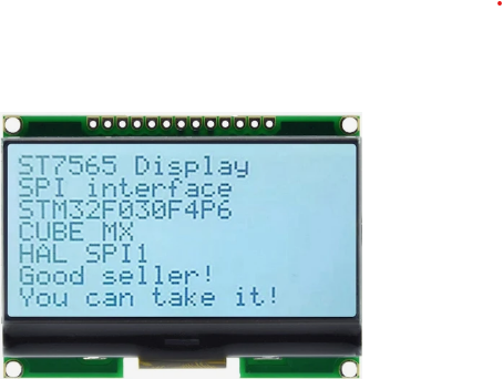
The ST7565 is a versatile graphic LCD controller designed to drive monochrome LCD displays. It supports a variety of resolutions, making it suitable for a wide range of applications. The controller is commonly used in embedded systems to display text, graphics, and custom images. Its built-in serial interface simplifies communication with microcontrollers, making it a popular choice for projects requiring compact and efficient display solutions.
Explore Projects Built with ST7565


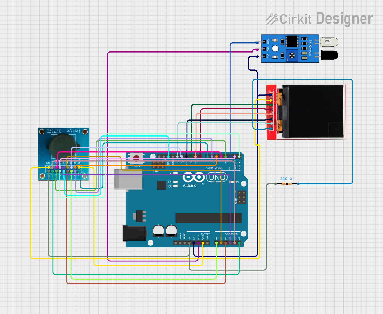
Explore Projects Built with ST7565
Common Applications and Use Cases
- Embedded systems and IoT devices
- Industrial control panels
- Handheld devices and portable instruments
- Consumer electronics with graphical user interfaces
- Educational and hobbyist projects
Technical Specifications
The ST7565 is a highly capable LCD controller with the following key specifications:
| Parameter | Value |
|---|---|
| Operating Voltage | 2.4V to 3.3V |
| Interface | Serial (SPI) and Parallel |
| Display Resolution | Up to 132x64 pixels |
| Operating Temperature | -20°C to +70°C |
| Current Consumption | ~0.3mA (typical, during operation) |
| LCD Bias Ratio | 1/9 to 1/65 |
| Built-in Oscillator | Yes |
| Memory | 65KB Display Data RAM |
Pin Configuration and Descriptions
The ST7565 has multiple pins for communication and control. Below is a table describing the key pins:
| Pin Name | Type | Description |
|---|---|---|
| VDD | Power | Positive power supply (2.4V to 3.3V). |
| VSS | Power | Ground connection. |
| CS | Input | Chip select signal. Active low. |
| A0 | Input | Data/Command control. High for data, low for command. |
| RST | Input | Reset signal. Active low. |
| SCL | Input | Serial clock input for SPI communication. |
| SDA | Input/Output | Serial data input/output for SPI communication. |
| DB0-DB7 | Input/Output | Parallel data bus (used in parallel mode). |
| VOUT | Power | Voltage output for LCD bias. |
| CAP1+, CAP1- | Power | Capacitor pins for internal voltage booster. |
| CAP2+, CAP2- | Power | Additional capacitor pins for voltage booster. |
| V1-V5 | Power | LCD bias voltage levels. |
Usage Instructions
The ST7565 is typically used in conjunction with a microcontroller, such as an Arduino UNO, to drive a graphic LCD. Below are the steps to use the ST7565 in a circuit:
1. Hardware Setup
- Power Supply: Connect the VDD pin to a 3.3V power source and the VSS pin to ground.
- Communication Interface: Use the SPI interface for communication:
- Connect the
CSpin to a digital output pin on the microcontroller. - Connect the
SCLpin to the SPI clock pin (e.g., Arduino pin 13). - Connect the
SDApin to the SPI data pin (e.g., Arduino pin 11). - Connect the
A0pin to a digital pin to toggle between data and command modes.
- Connect the
- Reset: Connect the
RSTpin to a digital pin for resetting the controller.
2. Software Setup
To control the ST7565, you can use libraries such as the Adafruit_ST7565 library. Below is an example Arduino sketch to initialize and display text on an ST7565-based LCD:
#include <Adafruit_GFX.h>       // Graphics library for text and shapes
#include <Adafruit_ST7565.h>    // Library for ST7565 controller

// Define pin connections
#define SCLK 13  // Serial clock pin
#define SID  11  // Serial data pin
#define A0   9   // Data/Command pin
#define RST  8   // Reset pin
#define CS   10  // Chip select pin

// Initialize the ST7565 display
Adafruit_ST7565 display(CS, RST, A0, SID, SCLK);

void setup() {
  display.begin(0x18);  // Initialize display with contrast value (0x18 is typical)
  display.clearDisplay();  // Clear the display buffer

  // Display text
  display.setTextSize(1);  // Set text size to 1 (smallest)
  display.setTextColor(BLACK);  // Set text color to black
  display.setCursor(0, 0);  // Set cursor to top-left corner
  display.print("Hello, ST7565!");  // Print text to the display
  display.display();  // Update the display with the buffer content
}

void loop() {
  // No actions in the loop for this example
}
3. Important Considerations
- Voltage Levels: Ensure the microcontroller's logic levels are compatible with the ST7565's 3.3V operating voltage. Use level shifters if necessary.
- Contrast Adjustment: The contrast value (e.g.,
0x18in the example) may need to be adjusted based on the display and operating conditions. - Capacitors: Properly connect external capacitors to the
CAP1+,CAP1-,CAP2+, andCAP2-pins for stable operation of the internal voltage booster.
Troubleshooting and FAQs
Common Issues and Solutions
Display Not Turning On
- Cause: Incorrect power supply or loose connections.
- Solution: Verify that the VDD and VSS pins are properly connected to a 3.3V power source and ground.
No Text or Graphics Displayed
- Cause: Incorrect initialization or communication settings.
- Solution: Ensure the SPI pins are correctly connected and the initialization code matches the hardware setup.
Flickering or Unstable Display
- Cause: Insufficient decoupling capacitors or unstable power supply.
- Solution: Add decoupling capacitors (e.g., 0.1µF) near the power pins and ensure a stable 3.3V supply.
Contrast Issues
- Cause: Incorrect contrast setting.
- Solution: Adjust the contrast value in the initialization code (
display.begin()).
FAQs
Can the ST7565 work with 5V microcontrollers like Arduino UNO?
- Yes, but you need level shifters to convert the 5V logic signals to 3.3V.
What is the maximum resolution supported by the ST7565?
- The ST7565 supports resolutions up to 132x64 pixels.
Can I use the ST7565 in parallel mode?
- Yes, the ST7565 supports both serial (SPI) and parallel communication modes. However, SPI is more commonly used due to its simplicity and fewer required pins.
How do I display custom graphics?
- Use a graphics library like
Adafruit_GFXto draw shapes or load bitmap images into the display buffer.
- Use a graphics library like
By following this documentation, you can effectively integrate the ST7565 into your projects and troubleshoot common issues.