How to Use Limit switch: Examples, Pinouts, and Specs
Introduction
A limit switch is an electromechanical device that operates based on the movement or presence of an object. It is designed to detect the presence or absence, passing, positioning, and end of travel of an object. When an object comes into contact with the actuator of the limit switch, it operates the contacts to make or break an electrical connection. Limit switches are commonly used in industrial control systems to control machinery and in various applications such as conveyor systems, elevators, and machine tools to provide precise control and positioning.
Explore Projects Built with Limit switch
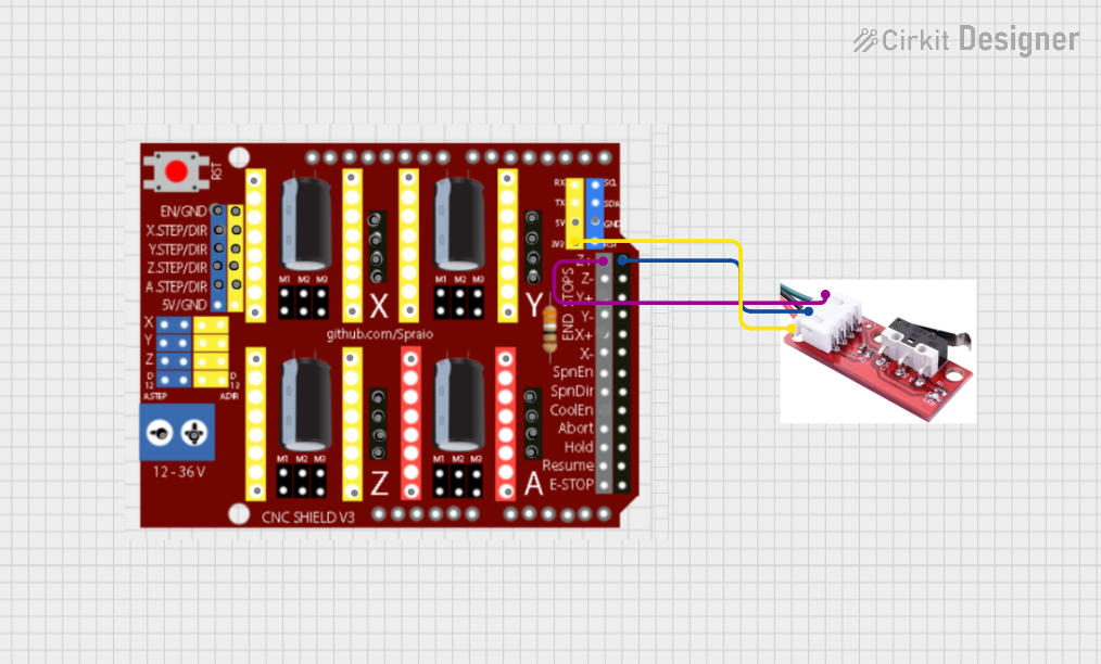
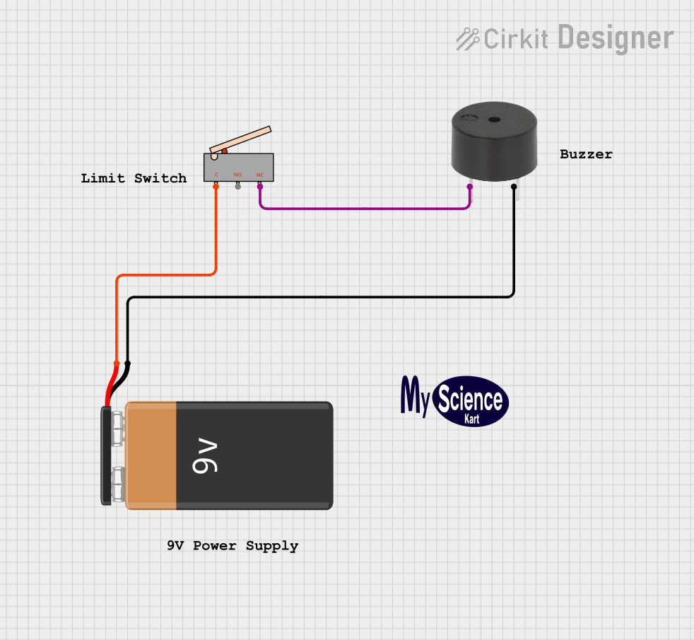
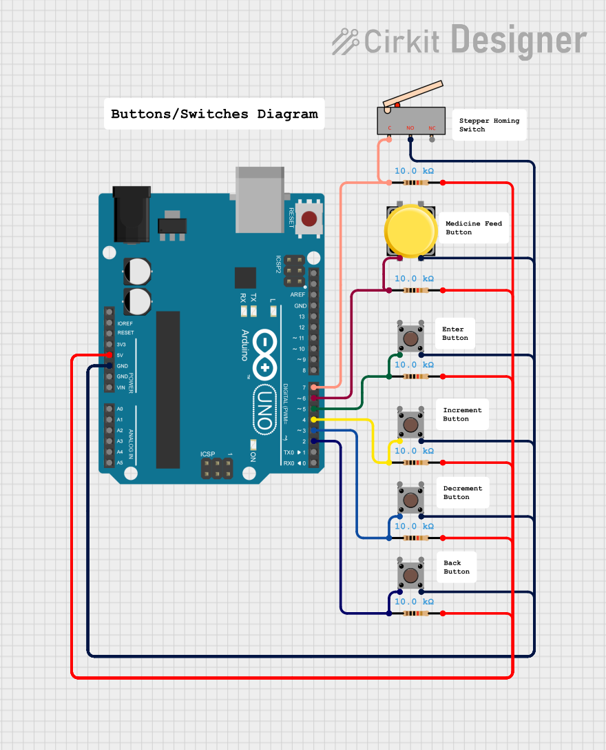
Explore Projects Built with Limit switch
Common Applications and Use Cases
- Industrial Automation: To control the movement of machinery parts.
- Safety Mechanisms: To prevent machinery from moving beyond safe operational limits.
- Position Sensing: To detect the presence or position of objects on a production line.
- End-of-Travel Detection: To signal when a mechanical part has reached its furthest allowable point.
Technical Specifications
Key Technical Details
- Voltage Rating: Typically ranges from 5V to 250V (AC or DC depending on the model).
- Current Rating: Commonly up to 10A, but can vary.
- Contact Configuration: Normally Open (NO), Normally Closed (NC), or both.
- Mechanical Life: Often rated for millions of actuations.
- Operating Temperature: Varies, but typically from -25°C to +70°C.
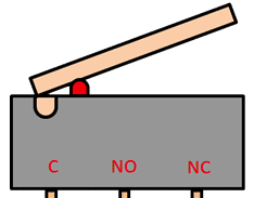
Pin Configuration and Descriptions
| Pin Number | Description | Notes |
|---|---|---|
| 1 | Common (COM) | Connects to the power supply or ground |
| 2 | Normally Closed (NC) | Closed when the switch is not actuated |
| 3 | Normally Open (NO) | Closed when the switch is actuated |
Usage Instructions
How to Use the Limit Switch in a Circuit
- Identify the Pins: Determine the COM, NO, and NC pins using the technical specifications.
- Wiring: Connect the COM pin to one side of the power supply. Connect the NO or NC pin to the load (e.g., relay, LED, motor) depending on whether you want the load to be powered when the switch is actuated or not.
- Mounting: Secure the limit switch in a position where the object or part will reliably actuate it.
- Testing: Test the switch by manually actuating it to ensure it operates the load as expected.
Important Considerations and Best Practices
- Debouncing: Mechanical switches can produce noise in the signal when they close; consider using a debouncing circuit or software to mitigate this.
- Load Ratings: Do not exceed the voltage and current ratings of the switch to avoid damage.
- Environmental Factors: Ensure the limit switch is suitable for the operating environment (e.g., dust, moisture, temperature).
- Regular Inspection: Periodically check the switch for wear and proper operation.
Troubleshooting and FAQs
Common Issues
- Switch Does Not Operate: Check for proper wiring and ensure that the switch is being actuated correctly.
- Intermittent Operation: Inspect for loose connections or damage to the switch.
- Excessive Noise: Implement debouncing techniques or check for electrical interference.
Solutions and Tips for Troubleshooting
- Check Connections: Ensure all wiring is secure and correct.
- Test with a Multimeter: Use a multimeter to check for continuity when the switch is actuated.
- Replace if Necessary: If the switch is damaged or worn out, replace it with a new one.
FAQs
Q: Can I use a limit switch with an Arduino? A: Yes, limit switches can be connected to an Arduino's digital input pins.
Q: What is the difference between NO and NC contacts? A: NO contacts close when the switch is actuated, while NC contacts open when actuated.
Q: How do I know if my limit switch is working? A: You can test it with a multimeter or by observing the operation of the connected load.
Example Arduino Code
Below is an example of how to use a limit switch with an Arduino UNO to control an LED:
// Define the connection pins
const int limitSwitchPin = 2; // Limit switch connected to pin 2
const int ledPin = 13;        // LED connected to pin 13

void setup() {
  pinMode(limitSwitchPin, INPUT_PULLUP); // Set the limit switch pin as input
  pinMode(ledPin, OUTPUT);               // Set the LED pin as output
}

void loop() {
  // Read the state of the limit switch
  bool isPressed = digitalRead(limitSwitchPin) == LOW;

  // If the switch is pressed, turn on the LED
  if (isPressed) {
    digitalWrite(ledPin, HIGH);
  } else {
    digitalWrite(ledPin, LOW);
  }
}
Note: The INPUT_PULLUP mode is used to enable the internal pull-up resistor, which is useful when using a NO limit switch. When the switch is open, the pin is pulled to a high state. When the switch is closed (actuated), it connects the pin to ground, resulting in a low state.