How to Use Gravity: Current to Voltage Module: Examples, Pinouts, and Specs
Introduction
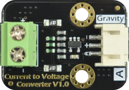
The Gravity: Current to Voltage Module (SEN0262) by DFRobot is an essential electronic component designed to convert current input into a proportional voltage output. This module is particularly useful in applications where current sensing is required, and a voltage signal is needed for interfacing with microcontrollers, data loggers, or other electronics that accept voltage inputs.
Explore Projects Built with Gravity: Current to Voltage Module
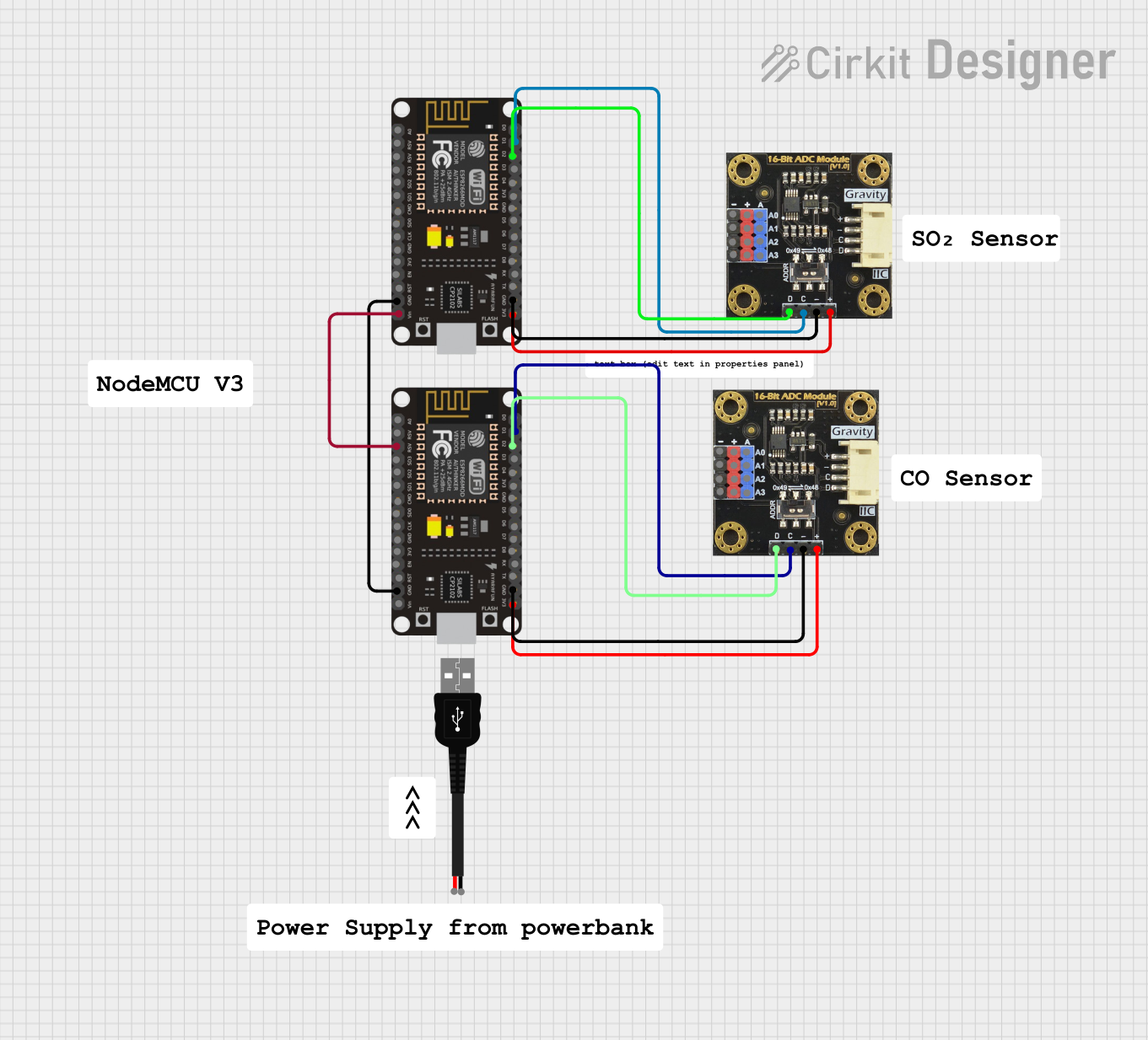


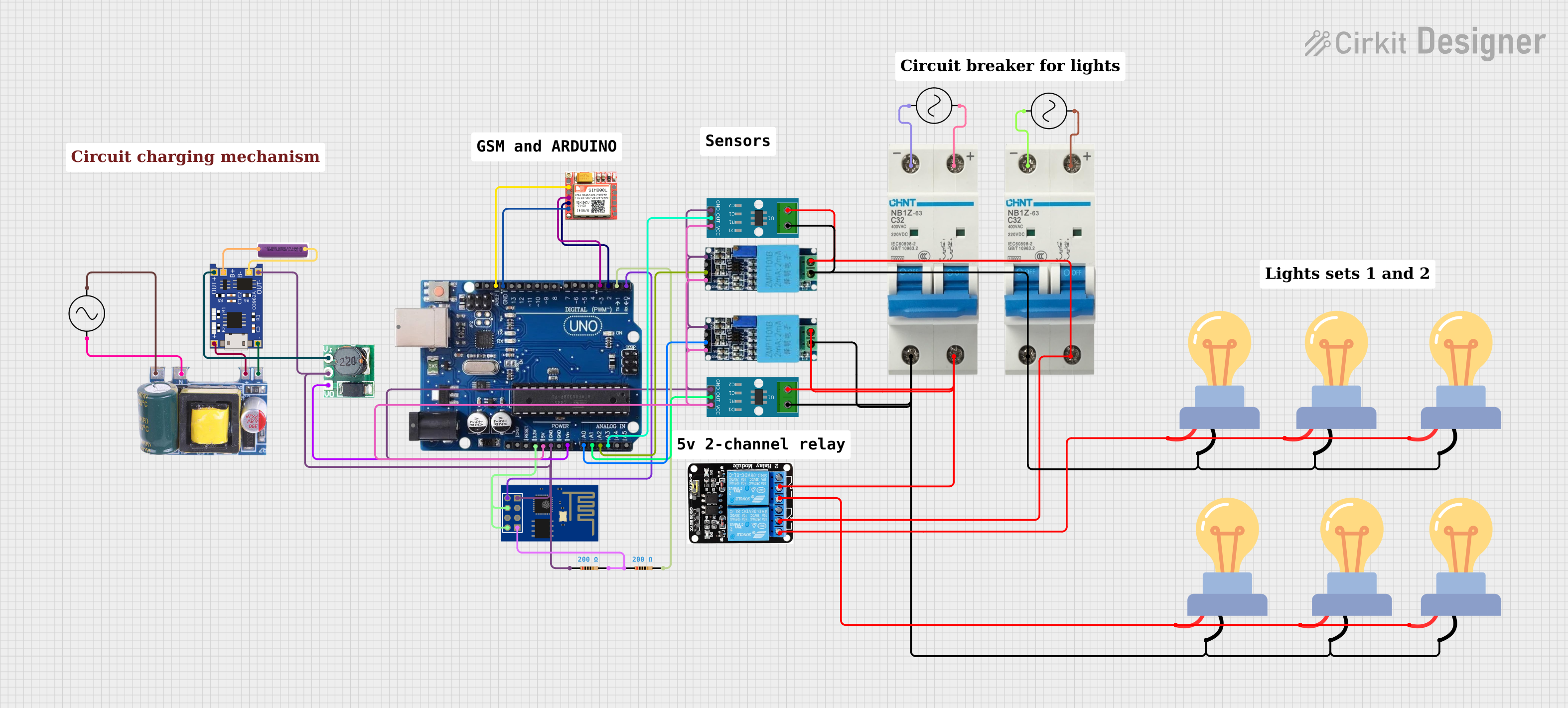
Explore Projects Built with Gravity: Current to Voltage Module
Common Applications and Use Cases:
- Monitoring electrical current in circuits
- Interfacing with microcontrollers like Arduino for data acquisition
- Industrial control systems
- Battery chargers and power supply monitoring
- Educational projects to demonstrate current sensing principles
Technical Specifications
The SEN0262 module is designed with precision and ease of use in mind. Below are the key technical details and pin configuration for the module.
Key Technical Details:
- Input Current Range: 0 to 5A (AC or DC)
- Output Voltage Range: 0 to 5V (linear relationship)
- Supply Voltage: 5V DC
- Sensitivity: 1V/A
- Non-linearity: ±2%
- Operating Temperature: -20°C to +70°C
Pin Configuration and Descriptions:
| Pin Number | Description | Notes |
|---|---|---|
| 1 | Signal Output (Vout) | Outputs voltage proportional to current |
| 2 | Ground (GND) | Connect to system ground |
| 3 | Power Supply (Vcc) | 5V DC input |
Usage Instructions
How to Use the Component in a Circuit:
Powering the Module:
- Connect the Vcc pin to a 5V power supply.
- Connect the GND pin to the common ground of your system.
Connecting the Current Source:
- The current to be measured should flow through the input terminals of the module.
Reading the Output Voltage:
- Connect the Vout pin to an analog input of a microcontroller, such as an Arduino, to read the voltage corresponding to the current.
Important Considerations and Best Practices:
- Ensure that the current does not exceed the maximum rating of 5A to prevent damage to the module.
- The power supply should be stable and regulated to ensure accurate readings.
- Avoid placing the module in environments with high electromagnetic interference.
- Use twisted pair wires for the input current to minimize noise pickup.
- Calibration may be necessary for precise applications.
Example Code for Arduino UNO
// Define the analog input pin connected to the module
const int currentSensorPin = A0;

void setup() {
  // Initialize serial communication at 9600 baud rate
  Serial.begin(9600);
}

void loop() {
  // Read the analog value from the sensor
  int sensorValue = analogRead(currentSensorPin);

  // Convert the analog reading (which goes from 0 - 1023) to a voltage (0 - 5V)
  float voltage = sensorValue * (5.0 / 1023.0);

  // Convert the voltage to current based on the sensitivity (1V/A)
  float current = voltage; // Since the sensitivity is 1V/A

  // Print the current value to the serial monitor
  Serial.print("Current: ");
  Serial.print(current);
  Serial.println(" A");

  // Wait for a bit to avoid spamming the serial monitor
  delay(1000);
}
Troubleshooting and FAQs
Common Issues Users Might Face:
- Inaccurate Readings: Ensure that the power supply is stable and that the module is not subjected to electromagnetic interference.
- No Output Voltage: Check all connections, including power to the module, and ensure that there is current flowing through the input terminals.
- Output Voltage Maxed Out: If the output voltage is at its maximum regardless of current, ensure the current does not exceed 5A and check for any short circuits.
Solutions and Tips for Troubleshooting:
- Calibration: If precision is required, calibrate the module using a known current source and adjust your readings accordingly.
- Noise Reduction: Use shielded cables and proper grounding to reduce noise.
- Check Connections: Loose connections can cause erratic readings. Ensure all connections are secure.
FAQs:
Q: Can the module measure both AC and DC current? A: Yes, the module can measure both AC and DC current within its specified range.
Q: What is the resolution of the module? A: The resolution depends on the analog-to-digital converter (ADC) of the microcontroller used. For a 10-bit ADC like that on the Arduino UNO, the resolution is 5V/1024 or approximately 4.88mV per bit.
Q: Is it necessary to power the module with exactly 5V? A: Yes, the module is designed to operate at 5V. Using a different voltage may result in inaccurate readings or damage to the module.
Q: Can I connect multiple modules to a single microcontroller? A: Yes, as long as there are enough analog input pins available on the microcontroller, you can connect multiple modules.
For further assistance, please refer to the DFRobot community forums or contact technical support.