How to Use 6n138: Examples, Pinouts, and Specs
Introduction
The 6N138 is an optocoupler (also known as an opto-isolator) that provides electrical isolation between its input and output. It consists of a light-emitting diode (LED) and a photodetector, allowing signals to be transmitted while preventing direct electrical connection. This component is commonly used in applications requiring signal isolation, such as interfacing between different voltage levels or protecting sensitive components from high voltages.
Explore Projects Built with 6n138

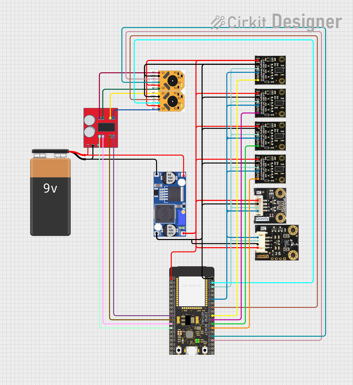
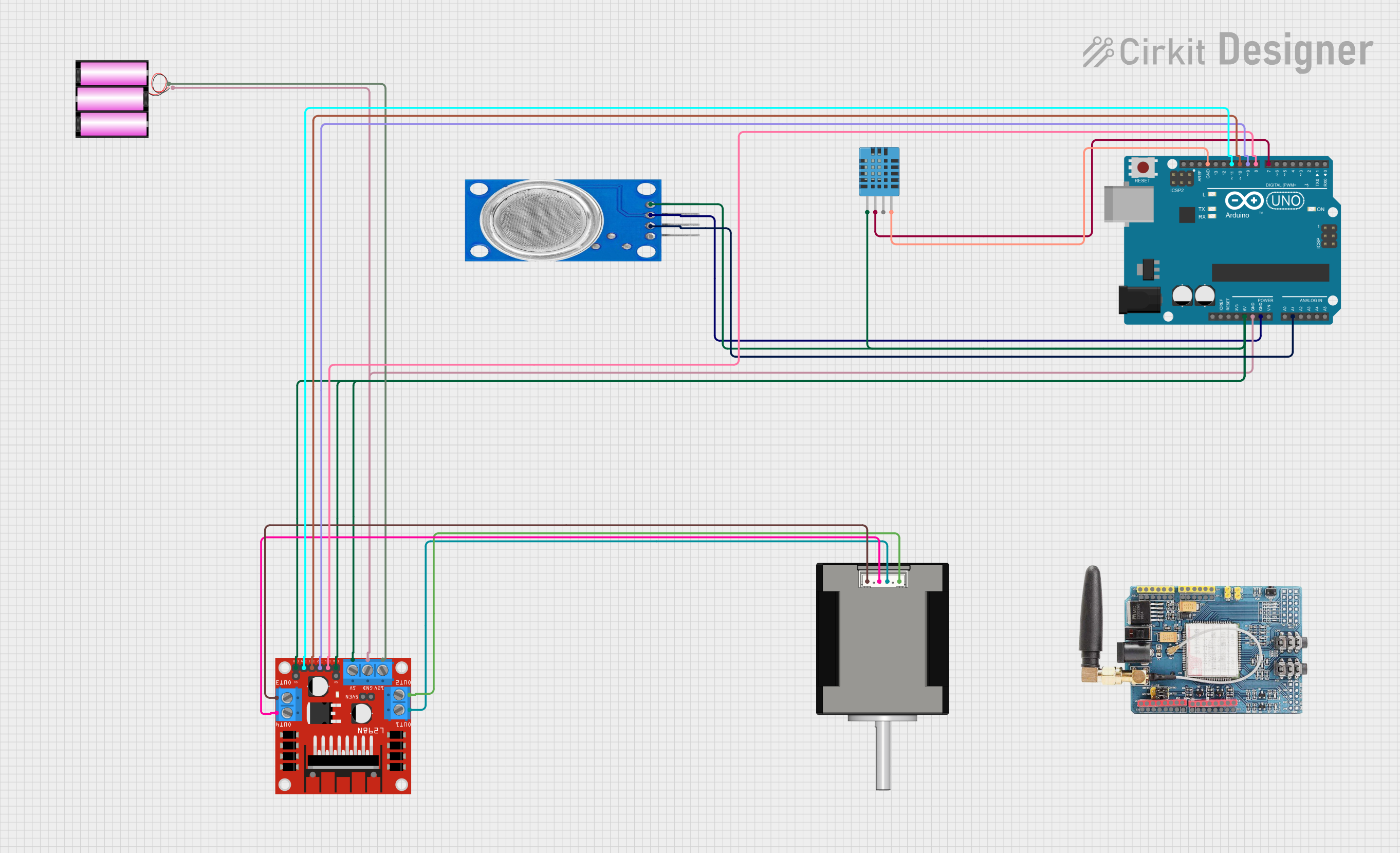
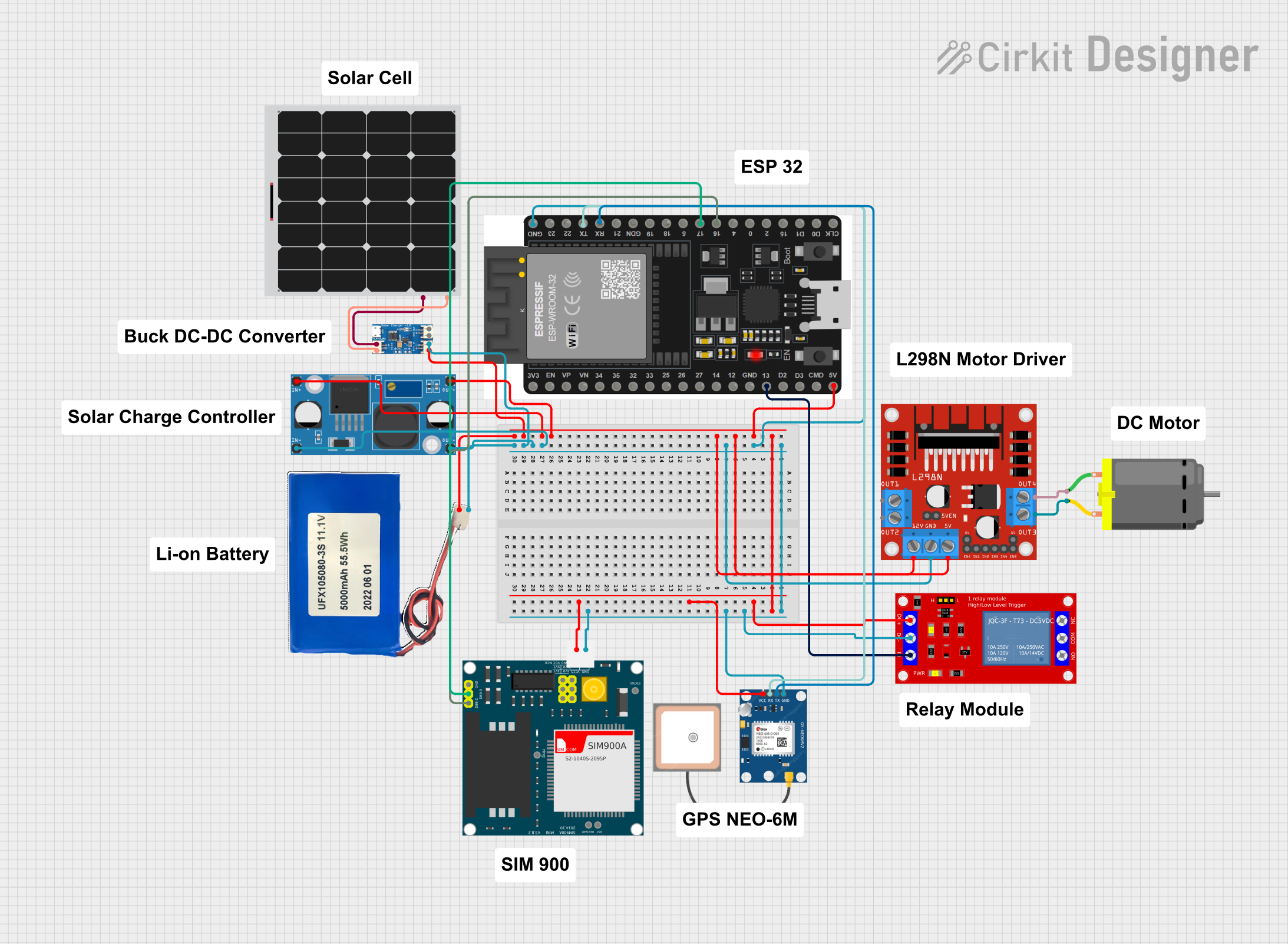
Explore Projects Built with 6n138
Common Applications and Use Cases
- Microcontroller interfacing with high-voltage circuits
- Signal isolation in industrial control systems
- Noise suppression in communication systems
- Protection of sensitive components from voltage spikes
- Interfacing between different logic levels (e.g., 5V to 3.3V systems)
Technical Specifications
Key Technical Details
- Input LED Forward Voltage (Vf): 1.2V (typical), 1.4V (maximum)
- Input LED Forward Current (If): 10mA (typical), 20mA (maximum)
- Output Collector-Emitter Voltage (Vce): 30V (maximum)
- Output Collector Current (Ic): 8mA (maximum)
- Current Transfer Ratio (CTR): 300% to 600% (typical)
- Isolation Voltage: 5000Vrms (minimum)
- Operating Temperature Range: -55°C to +100°C
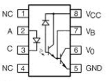
Pin Configuration and Descriptions
The 6N138 is an 8-pin DIP (Dual Inline Package) component. Below is the pinout and description:
| Pin Number | Pin Name | Description |
|---|---|---|
| 1 | Anode (LED) | Positive terminal of the input LED. Connect to the input signal. |
| 2 | Cathode (LED) | Negative terminal of the input LED. Connect to ground or a current-limiting resistor. |
| 3 | NC (No Connect) | Not connected internally. Leave unconnected or use as a mechanical support. |
| 4 | Emitter (Output) | Emitter terminal of the phototransistor. Typically connected to ground. |
| 5 | Collector (Output) | Collector terminal of the phototransistor. Connect to the output circuit. |
| 6 | Base (Optional) | Base terminal of the phototransistor. Can be left unconnected or used for biasing. |
| 7 | Vcc | Positive supply voltage for the output side. |
| 8 | GND | Ground connection for the output side. |
Usage Instructions
How to Use the 6N138 in a Circuit
Input Side (LED):
- Connect the anode (Pin 1) to the input signal through a current-limiting resistor. The resistor value can be calculated using Ohm's law:
R = (Vin - Vf) / If
For example, if the input voltage is 5V and the desired forward current is 10mA:R = (5V - 1.2V) / 0.01A = 380Ω(use the nearest standard resistor value, e.g., 390Ω). - Connect the cathode (Pin 2) to ground.
- Connect the anode (Pin 1) to the input signal through a current-limiting resistor. The resistor value can be calculated using Ohm's law:
Output Side (Phototransistor):
- Connect the collector (Pin 5) to the positive supply voltage (Vcc) through a pull-up resistor. The value of the pull-up resistor depends on the desired output current and speed.
- Connect the emitter (Pin 4) to ground.
- Optionally, connect the base (Pin 6) to a biasing resistor or leave it unconnected.
Power Supply:
- Connect Pin 7 (Vcc) to the positive supply voltage (e.g., 5V).
- Connect Pin 8 (GND) to ground.
Example Circuit with Arduino UNO
The following example demonstrates how to use the 6N138 to isolate a digital input signal for an Arduino UNO:
Circuit Connections
- Input Side:
- Connect Pin 1 (Anode) to a 5V signal source through a 390Ω resistor.
- Connect Pin 2 (Cathode) to ground.
- Output Side:
- Connect Pin 5 (Collector) to the Arduino digital input pin (e.g., D2) through a 10kΩ pull-up resistor.
- Connect Pin 4 (Emitter) to ground.
- Connect Pin 7 (Vcc) to the Arduino 5V pin.
- Connect Pin 8 (GND) to the Arduino GND pin.
Arduino Code Example
// Example code for using the 6N138 optocoupler with Arduino UNO
const int inputPin = 2; // Digital pin connected to the 6N138 output

void setup() {
  pinMode(inputPin, INPUT); // Set the input pin as an input
  Serial.begin(9600);       // Initialize serial communication at 9600 baud
}

void loop() {
  int signalState = digitalRead(inputPin); // Read the signal from the optocoupler
  if (signalState == HIGH) {
    Serial.println("Signal HIGH"); // Print message if signal is HIGH
  } else {
    Serial.println("Signal LOW");  // Print message if signal is LOW
  }
  delay(500); // Wait for 500ms before reading again
}
Important Considerations and Best Practices
- Always use a current-limiting resistor on the input LED to prevent damage.
- Ensure the pull-up resistor on the output side is appropriately sized for your application.
- Avoid exceeding the maximum ratings for voltage, current, and temperature.
- For high-speed applications, consider the effect of the pull-up resistor value on the rise time of the output signal.
Troubleshooting and FAQs
Common Issues and Solutions
No Output Signal:
- Check the input LED connections and ensure the current-limiting resistor is correctly calculated.
- Verify that the input signal voltage is sufficient to forward bias the LED (greater than 1.2V).
Output Signal is Always HIGH or LOW:
- Ensure the pull-up resistor is connected to the collector (Pin 5).
- Verify that the emitter (Pin 4) is properly grounded.
Slow Response Time:
- Reduce the value of the pull-up resistor to increase the speed of the output signal.
- Check if the input signal frequency is within the operating range of the 6N138.
Component Overheating:
- Ensure the input current does not exceed the maximum rating (20mA).
- Verify that the supply voltage (Vcc) is within the specified range.
FAQs
Q: Can the 6N138 be used for analog signal isolation?
A: The 6N138 is primarily designed for digital signal isolation. While it can transmit analog signals, the linearity and bandwidth may be limited.
Q: What is the purpose of the base pin (Pin 6)?
A: The base pin can be used for biasing the phototransistor to adjust its sensitivity or response time. In most cases, it can be left unconnected.
Q: How do I calculate the pull-up resistor value?
A: The pull-up resistor value depends on the desired output current and speed. A typical value is 10kΩ, but for faster response times, a lower value (e.g., 4.7kΩ) may be used.