How to Use Arduino UNO R4 Minima: Examples, Pinouts, and Specs
Introduction
The R4 Minima is a compact resistor designed for minimal space applications, offering reliable resistance values in a small footprint. Its small size and dependable performance make it an excellent choice for modern electronic circuits where space is a premium. The R4 Minima is widely used in consumer electronics, IoT devices, and compact embedded systems.
Explore Projects Built with Arduino UNO R4 Minima
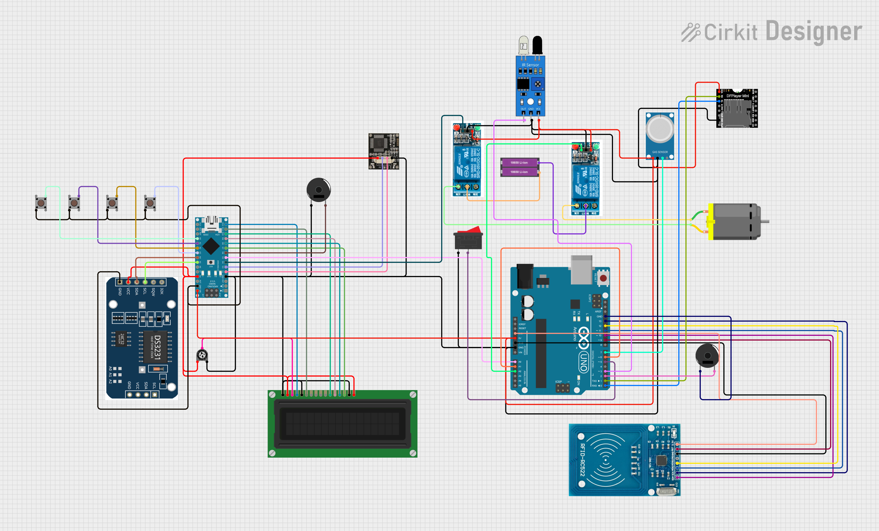
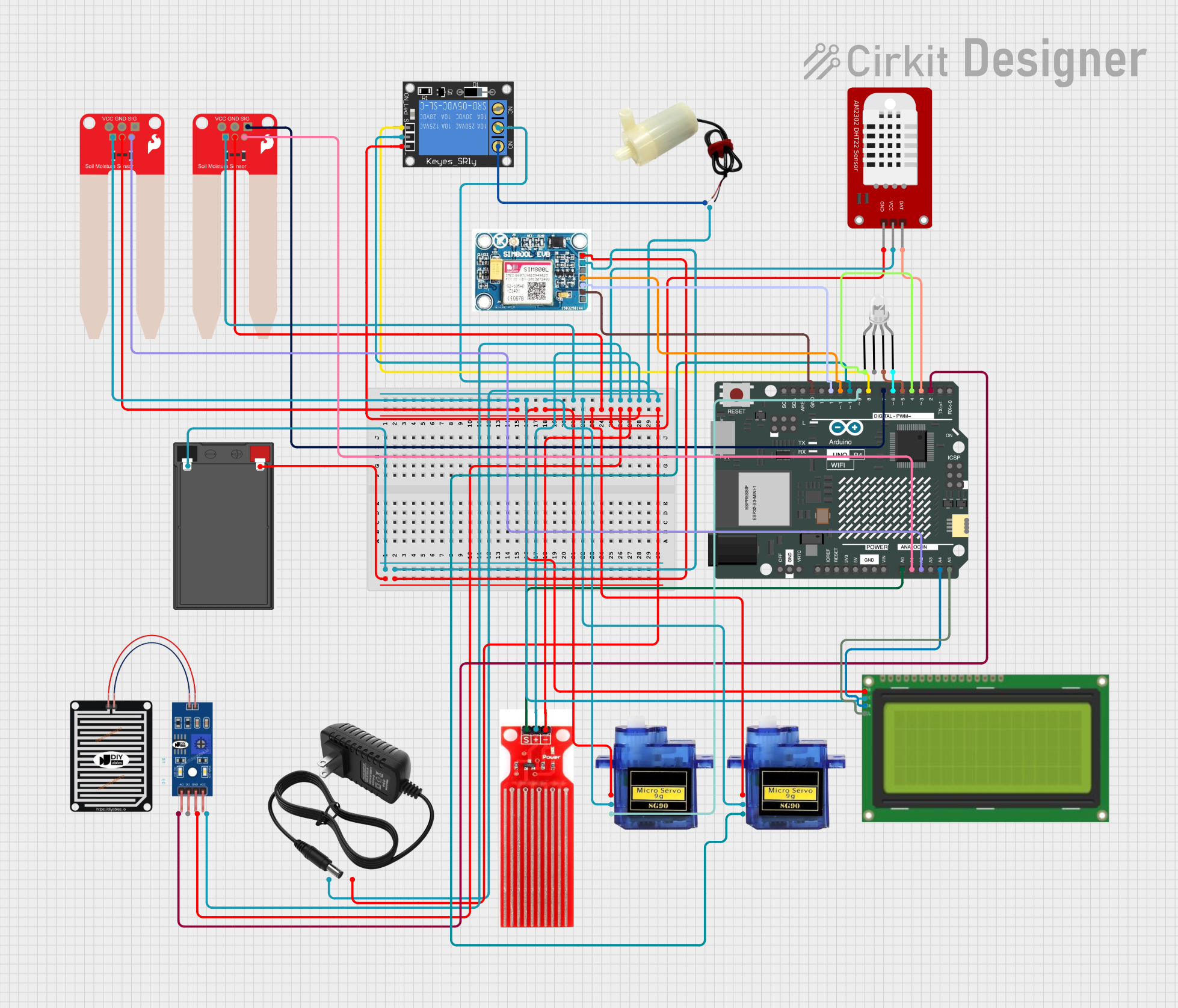
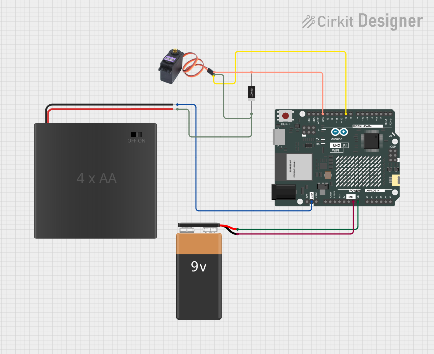
Explore Projects Built with Arduino UNO R4 Minima
Common Applications and Use Cases
- Space-constrained circuit designs
- Portable and wearable electronics
- IoT devices and smart home systems
- High-density PCBs in consumer electronics
- Signal conditioning and voltage division circuits
Technical Specifications
The R4 Minima is available in various resistance values and tolerances, making it versatile for a wide range of applications. Below are the key technical details:
General Specifications
| Parameter | Value |
|---|---|
| Resistance Range | 1 Ω to 1 MΩ |
| Tolerance | ±1%, ±5% |
| Power Rating | 0.125 W (1/8 W) |
| Temperature Coefficient | ±100 ppm/°C |
| Operating Temperature | -55°C to +155°C |
| Package Type | 0805 (SMD) |
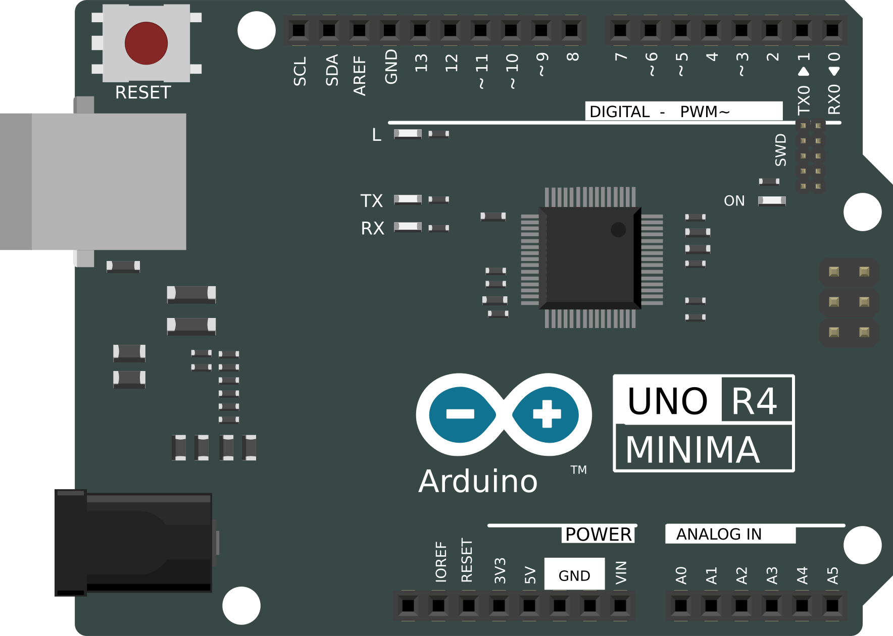
Pin Configuration and Descriptions
The R4 Minima is a surface-mount device (SMD) with two terminals. Below is the pin configuration:
| Pin Number | Description |
|---|---|
| 1 | Terminal 1 (Connect to circuit) |
| 2 | Terminal 2 (Connect to circuit) |
Usage Instructions
How to Use the R4 Minima in a Circuit
- Determine the Required Resistance Value: Select the appropriate resistance value based on your circuit design. For example, use Ohm's Law (V = IR) to calculate the resistance needed for current-limiting or voltage division.
- Soldering the Resistor:
- Place the R4 Minima on the PCB pads designed for 0805 SMD components.
- Use a soldering iron or reflow soldering process to secure the resistor in place.
- Verify Connections: Ensure that the resistor is properly connected to the circuit and that there are no soldering defects, such as cold joints or solder bridges.
Important Considerations and Best Practices
- Power Dissipation: Ensure that the resistor's power rating (0.125 W) is not exceeded. Calculate power dissipation using ( P = I^2R ) or ( P = V^2/R ).
- Temperature Effects: Be mindful of the temperature coefficient, especially in high-temperature environments, as resistance may vary slightly with temperature changes.
- Placement on PCB: Place the resistor away from heat-generating components to avoid thermal stress.
- ESD Precautions: Handle the resistor with care to prevent damage from electrostatic discharge.
Example: Using R4 Minima with an Arduino UNO
The R4 Minima can be used as a pull-up or pull-down resistor in Arduino circuits. Below is an example of using a 10 kΩ R4 Minima as a pull-down resistor for a push button:
// Example: Using R4 Minima as a pull-down resistor with Arduino UNO

const int buttonPin = 2;  // Pin connected to the push button
const int ledPin = 13;    // Pin connected to the onboard LED

void setup() {
  pinMode(buttonPin, INPUT);  // Set button pin as input
  pinMode(ledPin, OUTPUT);    // Set LED pin as output
}

void loop() {
  int buttonState = digitalRead(buttonPin);  // Read the button state

  if (buttonState == HIGH) {
    digitalWrite(ledPin, HIGH);  // Turn on LED if button is pressed
  } else {
    digitalWrite(ledPin, LOW);   // Turn off LED if button is not pressed
  }
}
Circuit Notes:
- Connect one terminal of the push button to pin 2 of the Arduino.
- Connect the other terminal of the push button to 5V.
- Place the R4 Minima (10 kΩ) between pin 2 and GND to act as a pull-down resistor.
Troubleshooting and FAQs
Common Issues and Solutions
Resistor Overheating:
- Cause: Exceeding the power rating of the resistor.
- Solution: Verify the power dissipation using ( P = I^2R ) or ( P = V^2/R ). Use a resistor with a higher power rating if necessary.
Incorrect Resistance Value:
- Cause: Using the wrong resistor or incorrect placement on the PCB.
- Solution: Double-check the resistor's value using a multimeter and ensure proper placement.
Soldering Issues:
- Cause: Cold solder joints or solder bridges.
- Solution: Inspect the solder joints under a magnifying glass and re-solder if needed.
Circuit Malfunction:
- Cause: Incorrect resistor placement or value.
- Solution: Verify the circuit design and ensure the resistor is connected as per the schematic.
FAQs
Q1: Can the R4 Minima be used in high-frequency circuits?
A1: Yes, the R4 Minima is suitable for high-frequency circuits due to its small size and low parasitic inductance.
Q2: What is the maximum voltage the R4 Minima can handle?
A2: The maximum voltage depends on the power rating and resistance value. For example, a 10 kΩ resistor with a 0.125 W rating can handle up to ( V = \sqrt{P \times R} = \sqrt{0.125 \times 10000} = 35.4 , \text{V} ).
Q3: Can I use the R4 Minima in a breadboard?
A3: The R4 Minima is an SMD component and is not directly compatible with breadboards. However, you can use an adapter or solder it to a breakout board for breadboard use.
Q4: How do I identify the resistance value of the R4 Minima?
A4: The resistance value is marked on the resistor body using a 3- or 4-digit code. Refer to an SMD resistor code chart to decode the value.
This concludes the documentation for the R4 Minima.