
How to Use MCP6S28: Examples, Pinouts, and Specs
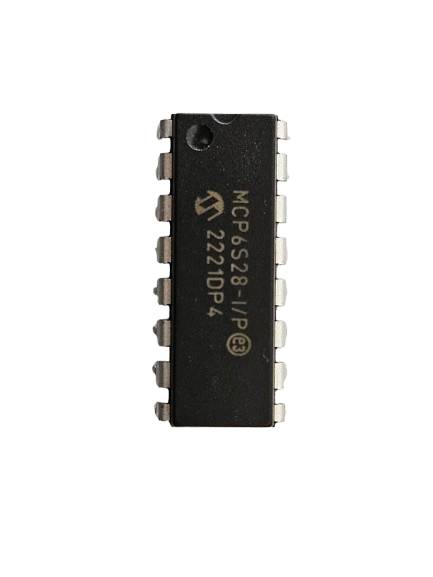
 Design with MCP6S28 in Cirkit Designer
Introduction
The MCP6S28 from Microchip is a versatile 4-channel programmable gain amplifier (PGA) with an SPI interface. This component is designed to select one of four analog input signals and route it to a single output while allowing for gain adjustments via digital control. It is commonly used in applications where signal amplification and multiplexing are required, such as in data acquisition systems, sensor interfaces, and audio processing.
Explore Projects Built with MCP6S28
 Open Project in Cirkit Designer
 Open Project in Cirkit Designer
 Open Project in Cirkit Designer
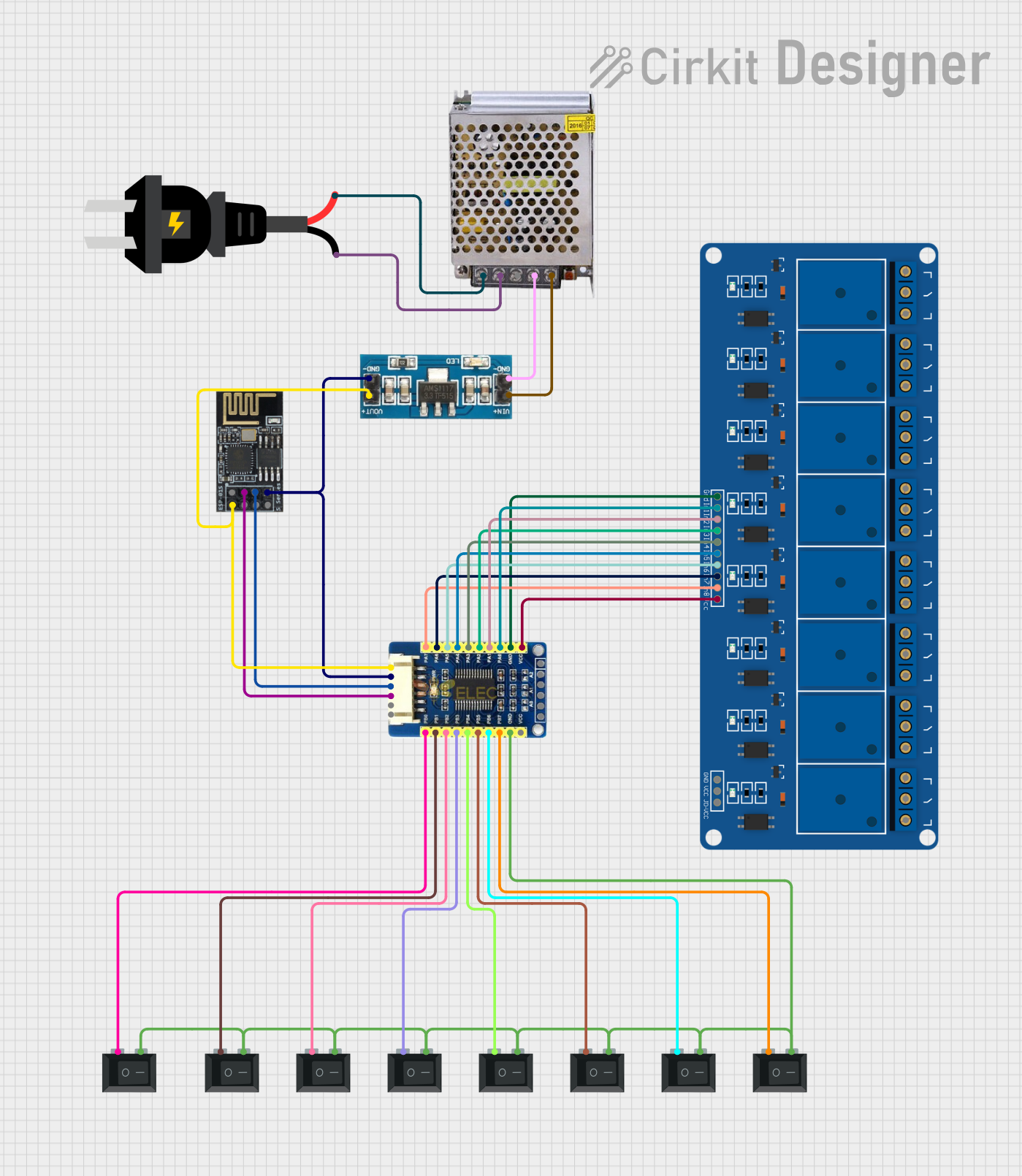
 Open Project in Cirkit Designer
Explore Projects Built with MCP6S28

 Open Project in Cirkit Designer
 Open Project in Cirkit Designer
 Open Project in Cirkit Designer
 Open Project in Cirkit Designer
Common Applications
- Data acquisition systems
- Sensor signal conditioning
- Audio processing and mixing
- Medical instrumentation
- Industrial control systems
Technical Specifications
Key Technical Details
- Supply Voltage: 2.5V to 5.5V
- Gain Selection: 1, 2, 4, 5, 8, 10, 16, or 32 times
- Input Offset Voltage: 150 µV (max)
- Bandwidth: Up to 2 MHz
- Low Current Consumption: 1 mA (typical)
- Extended Temperature Range: -40°C to +125°C
Pin Configuration and Descriptions
| Pin Number | Name | Description |
|---|---|---|
| 1 | CS | Chip Select (active low) |
| 2 | SCK | Serial Clock Input |
| 3 | SDI | Serial Data Input |
| 4 | Vss | Ground |
| 5 | CH0 | Analog Input Channel 0 |
| 6 | CH1 | Analog Input Channel 1 |
| 7 | CH2 | Analog Input Channel 2 |
| 8 | CH3 | Analog Input Channel 3 |
| 9 | Vout | Analog Output |
| 10 | Vdd | Positive Power Supply |
Usage Instructions
How to Use the MCP6S28 in a Circuit
- Power Supply: Connect Vdd to a 2.5V to 5.5V power supply and Vss to ground.
- SPI Interface: Connect CS, SCK, and SDI to the corresponding SPI pins on your microcontroller.
- Analog Inputs: Connect the analog signals to CH0 through CH3 as required.
- Analog Output: Connect Vout to the next stage in your signal processing chain.
- Programming: Use the SPI interface to send commands to the MCP6S28 to select the desired channel and gain.
Important Considerations and Best Practices
- Ensure that the power supply is within the specified range and is stable.
- Keep analog signal paths as short as possible to minimize noise pickup.
- Use proper decoupling capacitors close to the Vdd and Vss pins to filter out power supply noise.
- When designing the PCB, keep digital and analog sections separate to reduce interference.
- Ensure that the SPI clock speed does not exceed the maximum frequency specified by the datasheet.
Example Code for Arduino UNO
#include <SPI.h>

// MCP6S28 SPI Commands
const byte MCP6S28_WRITE_CMD = 0x40; // Write command for MCP6S28
const byte MCP6S28_GAIN_CMD = 0x00;  // Gain setting command

// SPI Pin Definitions
const int CS_PIN = 10; // Chip Select pin for MCP6S28

void setup() {
  // Initialize SPI
  SPI.begin();
  pinMode(CS_PIN, OUTPUT);
  digitalWrite(CS_PIN, HIGH); // Deselect the MCP6S28
}

void loop() {
  // Select channel 0 and set gain to 1
  setPGAChannelAndGain(0, 1);
  // Add your application code here
}

void setPGAChannelAndGain(byte channel, byte gain) {
  // Ensure channel is within 0-3 and gain is a valid value
  channel = channel & 0x03;
  gain = gain & 0x0F;

  // Start SPI transaction
  digitalWrite(CS_PIN, LOW);
  SPI.transfer(MCP6S28_WRITE_CMD); // Send write command
  SPI.transfer((channel << 4) | gain); // Send channel and gain settings
  digitalWrite(CS_PIN, HIGH); // End SPI transaction
}
Troubleshooting and FAQs
Common Issues
- No Output Signal: Ensure that the correct channel is selected and that the gain is set appropriately. Also, check the power supply and SPI connections.
- Signal Distortion: Verify that the input signal does not exceed the voltage range of the selected channel. Also, check for proper grounding and decoupling.
- Communication Errors: Make sure that the SPI clock frequency is within the specified limits and that the CS, SCK, and SDI connections are secure.
Solutions and Tips for Troubleshooting
- Double-check all connections and ensure that solder joints are solid and free of shorts.
- Use an oscilloscope to verify the SPI signals and the analog output.
- If experiencing noise issues, consider adding shielding to analog signal lines and using twisted-pair wires.
FAQs
Q: Can the MCP6S28 be used with a single-ended and differential input? A: Yes, the MCP6S28 can be configured for both single-ended and differential inputs.
Q: What is the maximum SPI clock frequency for the MCP6S28? A: The maximum SPI clock frequency is 10 MHz.
Q: How do I change the gain setting? A: Gain settings can be changed by sending the appropriate command and data via the SPI interface, as shown in the example code.
Q: Is the MCP6S28 suitable for high-precision applications? A: The MCP6S28 is suitable for many precision applications, but the suitability depends on the specific requirements of the application, such as noise performance and bandwidth.