How to Use 556 Timer IC: Examples, Pinouts, and Specs
Introduction
The 556 Timer IC, manufactured by Texas Instruments (Part ID: NE556), is a dual-timer integrated circuit that combines two independent 555 timer circuits in a single 14-pin package. This versatile component is widely used in applications such as pulse generation, time delay, frequency modulation, and oscillation. Its dual-timer design allows for compact and efficient circuit designs, making it a popular choice for hobbyists and professionals alike.
Explore Projects Built with 556 Timer IC
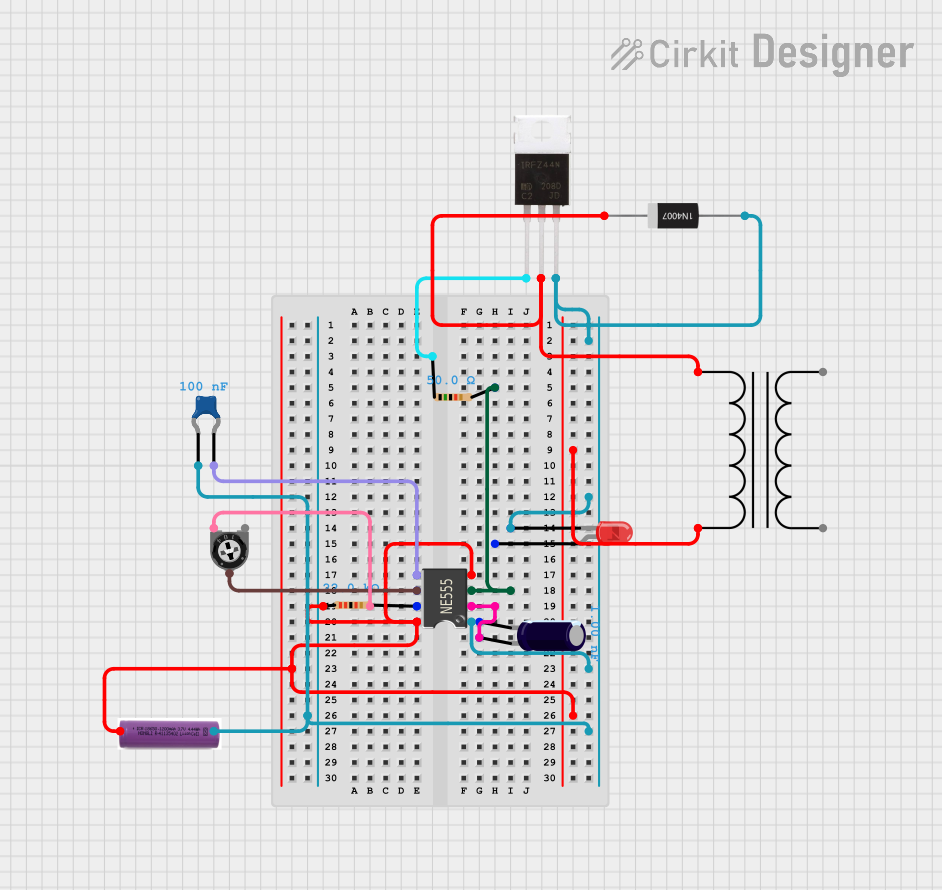
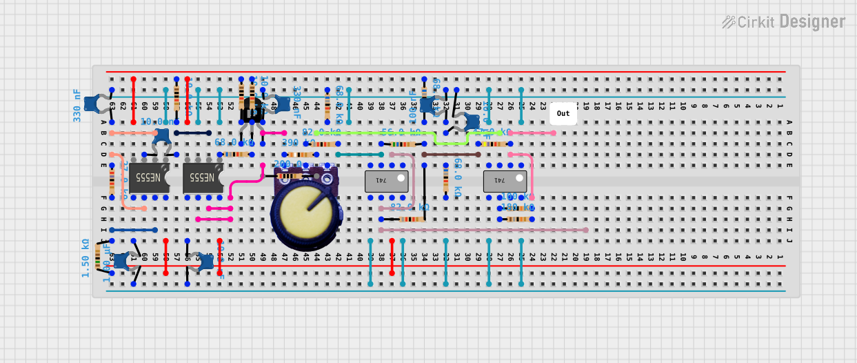
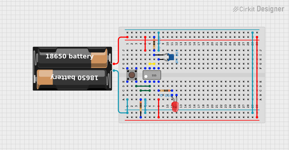
Explore Projects Built with 556 Timer IC
Common Applications
- Monostable (one-shot) and astable (oscillator) multivibrator circuits
- Pulse-width modulation (PWM) and frequency generation
- Time delay circuits
- LED and motor control
- Signal generation and waveform shaping
Technical Specifications
The following table outlines the key technical specifications of the NE556 Timer IC:
| Parameter | Value |
|---|---|
| Supply Voltage (Vcc) | 4.5V to 16V |
| Supply Current (per timer) | 10mA (typical) |
| Output Current (per timer) | 200mA (maximum) |
| Operating Temperature Range | 0°C to 70°C |
| Timing Capacitor Range | 0.001µF to 100µF |
| Timing Resistor Range | 1kΩ to 10MΩ |
| Package Type | 14-pin Dual In-line Package (DIP) |
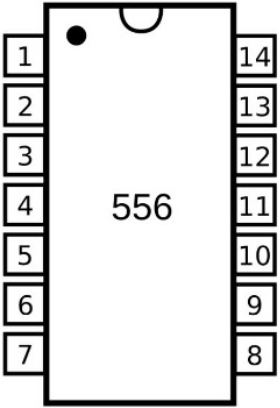
Pin Configuration and Descriptions
The NE556 Timer IC has 14 pins, with each timer circuit having its own set of control pins. The pin configuration is as follows:
| Pin Number | Pin Name | Description |
|---|---|---|
| 1 | GND | Ground (0V reference) |
| 2 | TRIG (Timer 1) | Trigger input for Timer 1; starts timing cycle when voltage drops below 1/3 Vcc |
| 3 | OUT (Timer 1) | Output of Timer 1 |
| 4 | RESET (Timer 1) | Resets Timer 1 when pulled low |
| 5 | CTRL (Timer 1) | Control voltage for Timer 1; adjusts threshold voltage |
| 6 | THRS (Timer 1) | Threshold input for Timer 1; ends timing cycle when voltage exceeds 2/3 Vcc |
| 7 | DISCH (Timer 1) | Discharge pin for Timer 1; discharges timing capacitor |
| 8 | Vcc | Positive supply voltage |
| 9 | DISCH (Timer 2) | Discharge pin for Timer 2; discharges timing capacitor |
| 10 | THRS (Timer 2) | Threshold input for Timer 2; ends timing cycle when voltage exceeds 2/3 Vcc |
| 11 | CTRL (Timer 2) | Control voltage for Timer 2; adjusts threshold voltage |
| 12 | RESET (Timer 2) | Resets Timer 2 when pulled low |
| 13 | OUT (Timer 2) | Output of Timer 2 |
| 14 | TRIG (Timer 2) | Trigger input for Timer 2; starts timing cycle when voltage drops below 1/3 Vcc |
Usage Instructions
The NE556 Timer IC can be used in a variety of circuit configurations. Below are general steps and considerations for using the component:
Using the NE556 in a Circuit
- Power Supply: Connect pin 8 (Vcc) to the positive supply voltage (4.5V to 16V) and pin 1 (GND) to ground.
- Timer Configuration:
- For monostable mode, connect the TRIG pin to a trigger signal and use a resistor-capacitor (RC) network between the THRS and DISCH pins to set the timing interval.
- For astable mode, connect the TRIG and THRS pins together and use an RC network to set the oscillation frequency.
- Output: The OUT pin provides the timer's output signal. It can drive LEDs, relays, or other components directly (up to 200mA).
- Reset: The RESET pin can be used to terminate the timing cycle prematurely. If unused, connect it to Vcc to avoid accidental resets.
- Control Voltage: The CTRL pin can be used to adjust the threshold voltage. If unused, connect it to ground via a 0.01µF capacitor for stability.
Example: Astable Mode with Arduino UNO
The following example demonstrates how to use the NE556 Timer IC in astable mode to generate a square wave, which is then read by an Arduino UNO.
Circuit Connections
- Connect pin 8 (Vcc) to 5V and pin 1 (GND) to ground.
- Connect a 10kΩ resistor between pin 7 (DISCH) and pin 8 (Vcc).
- Connect a 100kΩ resistor between pin 7 (DISCH) and pin 6 (THRS).
- Connect a 10µF capacitor between pin 6 (THRS) and ground.
- Connect pin 6 (THRS) to pin 2 (TRIG).
- Connect pin 3 (OUT) to an Arduino UNO digital input pin (e.g., pin 2).
Arduino Code
// This code reads the square wave output from the NE556 Timer IC
// and toggles an LED connected to pin 13 based on the signal.

const int timerOutputPin = 2; // NE556 output connected to Arduino pin 2
const int ledPin = 13;        // LED connected to pin 13

void setup() {
  pinMode(timerOutputPin, INPUT); // Set timer output pin as input
  pinMode(ledPin, OUTPUT);        // Set LED pin as output
}

void loop() {
  int timerState = digitalRead(timerOutputPin); // Read the timer output
  digitalWrite(ledPin, timerState);             // Set LED state to match timer output
}
Best Practices
- Use decoupling capacitors (e.g., 0.1µF) near the Vcc pin to reduce noise and improve stability.
- Ensure the timing capacitor and resistor values are within the recommended range for accurate operation.
- Avoid leaving unused pins floating; connect them to appropriate voltage levels.
Troubleshooting and FAQs
Common Issues
No Output Signal:
- Verify that the power supply voltage is within the specified range (4.5V to 16V).
- Check all connections, especially the RC network and trigger input.
- Ensure the RESET pin is connected to Vcc if not in use.
Unstable Timing:
- Use high-quality capacitors with low leakage for the timing circuit.
- Add a decoupling capacitor (0.1µF) near the Vcc pin to reduce noise.
Output Voltage Too Low:
- Ensure the load connected to the output pin does not exceed the maximum current rating (200mA).
- Check for short circuits or incorrect wiring.
FAQs
Q: Can the NE556 Timer IC operate with a 3.3V power supply?
A: No, the minimum supply voltage for the NE556 is 4.5V. For 3.3V applications, consider using a low-voltage timer IC.
Q: How do I calculate the frequency in astable mode?
A: The frequency is given by the formula:
[
f = \frac{1.44}{(R1 + 2R2) \cdot C}
]
where ( R1 ) and ( R2 ) are the resistors, and ( C ) is the capacitor in the RC network.
Q: Can I use both timers independently?
A: Yes, the NE556 contains two independent 555 timers that can be configured separately for different applications.