How to Use Adafruit Perma Proto Small Mint: Examples, Pinouts, and Specs
Introduction
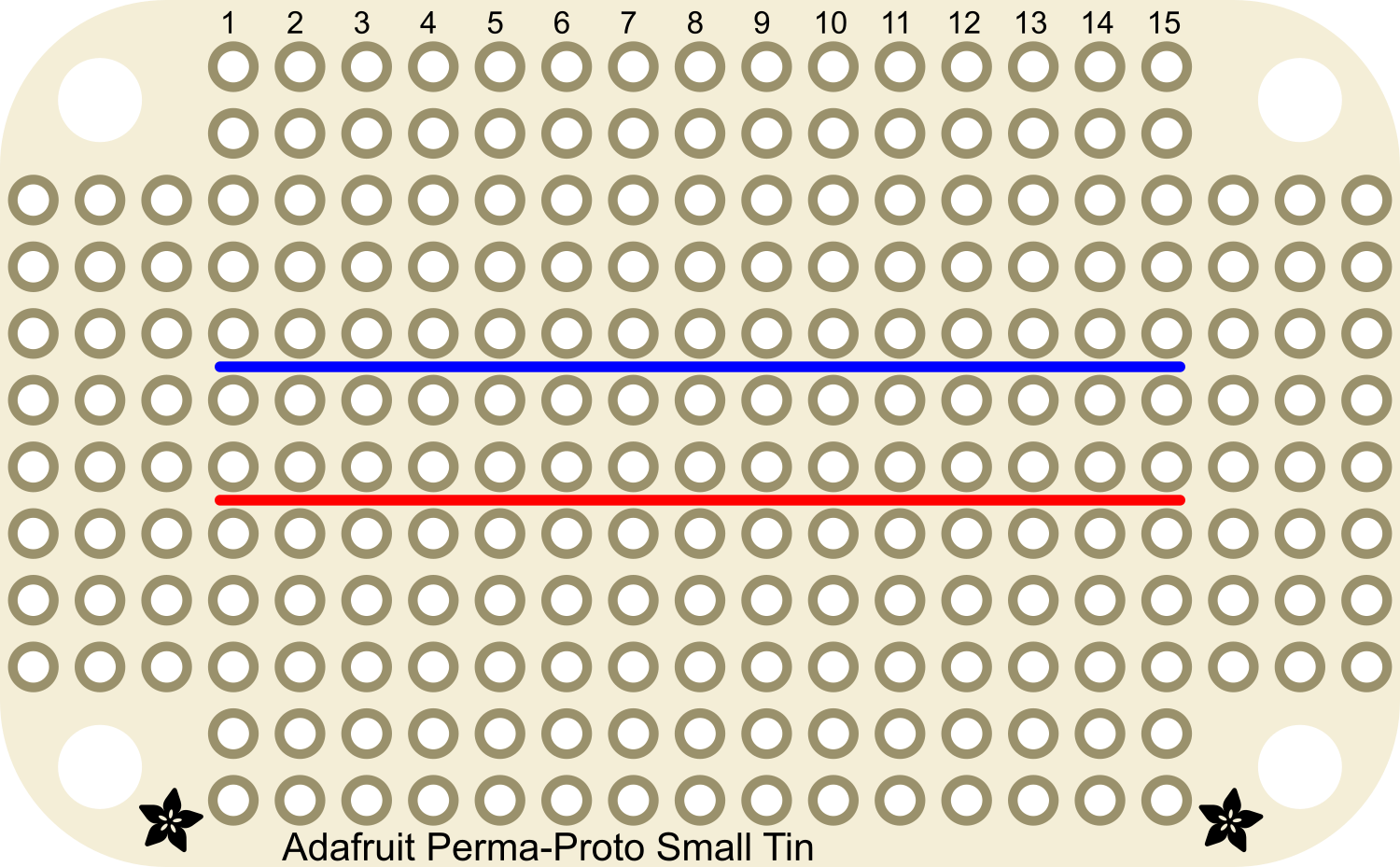
The Adafruit Perma Proto Small Mint is a compact, solderable prototyping board designed for creating permanent prototypes and electronic circuits. Its layout mirrors that of a standard breadboard, with interconnected holes spaced at a standard 0.1-inch (2.54mm) grid, allowing for easy transfer of circuits from a breadboard to a more durable and permanent platform. This board is ideal for small projects where space is at a premium and for hobbyists who want to give their temporary breadboard projects a long-lasting form.
Explore Projects Built with Adafruit Perma Proto Small Mint
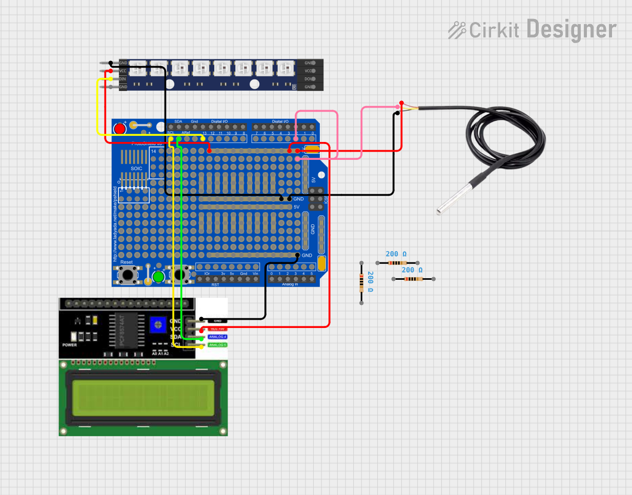


Explore Projects Built with Adafruit Perma Proto Small Mint
Common Applications and Use Cases
- Permanent circuit prototypes
- Small electronic projects
- Educational purposes for learning soldering and circuit design
- DIY electronics, such as custom controllers, wearables, and IoT devices
Technical Specifications
Key Technical Details
- Dimensions: 1.8" x 1.4" x 0.0625" (46mm x 36mm x 1.6mm)
- Hole Spacing: 0.1" (2.54mm)
- Hole Diameter: Approximately 0.038" (0.97mm)
- Material: FR4 with a green solder mask
- Copper Thickness: 1 oz per square foot
- Plating: Tin
- Number of Holes: 160 total (20 rows of 8 holes each)
Pin Configuration and Descriptions
The Adafruit Perma Proto Small Mint does not have a traditional pin configuration as it is a prototyping board. However, the board features a series of interconnected holes that are grouped as follows:
| Group | Description |
|---|---|
| Power Rails | Two sets of horizontal lines along the edges for power distribution |
| Vertical Strips | 5-hole vertical strips that are electrically connected, mimicking a breadboard's layout |
Usage Instructions
How to Use the Component in a Circuit
Design Your Circuit: Begin by designing your circuit on a breadboard or schematic software to ensure proper functionality before transferring it to the Perma Proto board.
Transfer the Design: Once the design is tested, transfer the layout to the Perma Proto board by placing components in the same relative positions.
Soldering: Solder the components onto the board. Use a soldering iron with a fine tip and solder with a small diameter to make precise connections.
Connect the Components: Use jumper wires or cut small pieces of solid-core wire to make connections between the components following your design.
Power Distribution: Utilize the power rails for distributing power and ground connections across the board.
Final Inspection: After soldering, inspect all connections for cold solder joints or shorts. Use a multimeter to check for continuity and correct any issues.
Important Considerations and Best Practices
- Soldering: Ensure that the soldering iron is at the correct temperature (around 350°C) and that you use lead-free solder for environmental reasons.
- Component Orientation: Pay attention to the polarity of components like diodes, capacitors, and ICs.
- Trace Current: Be mindful of the current each trace will carry to avoid damage.
- Inspection: Regularly inspect the board for solder bridges or loose connections.
- Safety: Always work in a well-ventilated area when soldering.
Troubleshooting and FAQs
Common Issues Users Might Face
- Cold Solder Joints: A dull or grainy appearance may indicate a bad solder joint. Reheat the joint and add a small amount of solder if necessary.
- Short Circuits: Use a magnifying glass to inspect for accidental solder bridges between adjacent pads.
- Component Malfunction: If a component isn't working, check its orientation and solder connections.
Solutions and Tips for Troubleshooting
- Desoldering: If you need to remove a component, use desoldering braid or a desoldering pump to clear the solder from the pad and pin.
- Testing: Use a multimeter to test connections and ensure that there are no shorts or opens in the circuit.
- Reflowing Solder: If a connection looks suspect, reflow the solder by reheating the joint and adding a small amount of fresh solder.
FAQs
Q: Can I reuse the Perma Proto board? A: The board is intended for permanent use, but components can be desoldered with care. However, the board may be damaged through multiple soldering cycles.
Q: Is the board breadboard-compatible? A: Yes, the layout is designed to mimic a breadboard, making it easy to transfer circuits directly.
Q: How much current can the traces handle? A: The traces can handle a few hundred milliamps of current. For higher currents, reinforce the traces with additional solder or use external wires.
Q: Can I cut the board to a smaller size? A: Yes, the board can be cut using a PCB shear or a fine-toothed saw, but be cautious of creating sharp edges and damaging the layout.
For any further assistance or questions, please refer to the Adafruit community forums or contact Adafruit support.