How to Use Reed Switch Module: Examples, Pinouts, and Specs
Introduction
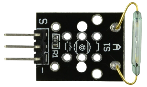
A Reed Switch Module consists of a reed switch encapsulated in a protective housing, often with additional circuitry. The reed switch is a small, sealed glass tube containing two ferromagnetic metal contacts that close or open in response to a magnetic field. This module is widely used for sensing applications due to its simplicity, reliability, and low power consumption.
Explore Projects Built with Reed Switch Module
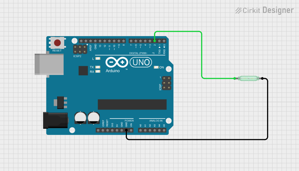
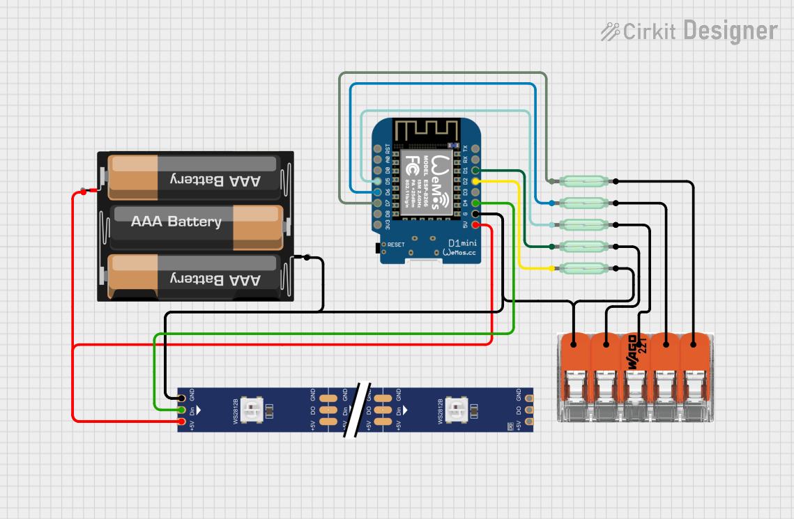
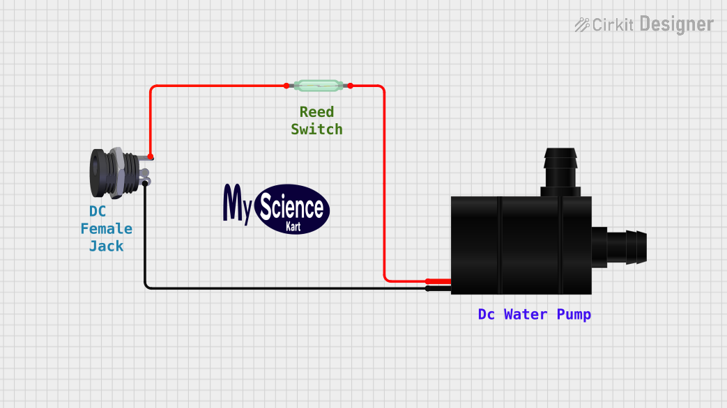
Explore Projects Built with Reed Switch Module
Common Applications and Use Cases
- Security systems (e.g., door/window sensors)
- Position or proximity detection
- Robotics (e.g., detecting magnetic objects)
- Industrial automation
- Home automation (e.g., smart doors or cabinets)
Technical Specifications
Below are the key technical details of a typical Reed Switch Module:
| Parameter | Value |
|---|---|
| Operating Voltage | 3.3V to 5V |
| Operating Current | < 10mA |
| Output Type | Digital (High/Low) |
| Trigger Mechanism | Magnetic field |
| Dimensions | Varies by manufacturer (e.g., 32mm x 14mm) |
| Response Time | Typically < 1ms |
| Contact Rating | 10W (max), 200V (max), 0.5A (max) |
Pin Configuration and Descriptions
The Reed Switch Module typically has three pins:
| Pin | Name | Description |
|---|---|---|
| 1 | VCC | Power supply pin (3.3V to 5V) |
| 2 | GND | Ground pin |
| 3 | OUT | Digital output pin (HIGH when no magnet, LOW when magnet is near) |
Usage Instructions
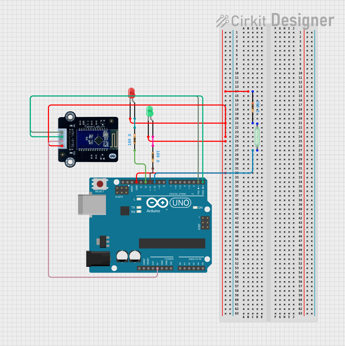
How to Use the Reed Switch Module in a Circuit
Connect the Module to Power:
- Connect the
VCCpin to a 3.3V or 5V power source. - Connect the
GNDpin to the ground of your circuit.
- Connect the
Connect the Output Pin:
- Connect the
OUTpin to a digital input pin of your microcontroller (e.g., Arduino UNO). - Use a pull-up resistor if required (some modules may already include one).
- Connect the
Place a Magnet Near the Reed Switch:
- When a magnet is brought close to the reed switch, the contacts inside the switch close, and the
OUTpin goes LOW. - When the magnet is removed, the contacts open, and the
OUTpin goes HIGH.
- When a magnet is brought close to the reed switch, the contacts inside the switch close, and the
Important Considerations and Best Practices
- Magnet Placement: Ensure the magnet is aligned properly with the reed switch for reliable operation.
- Debouncing: Reed switches may produce noise or "bouncing" when switching states. Use software debouncing in your code if necessary.
- Avoid Overloading: Do not exceed the contact rating of the reed switch to prevent damage.
- Environmental Factors: Protect the module from excessive vibration, as it may cause false triggering.
Example Code for Arduino UNO
Below is an example of how to use the Reed Switch Module with an Arduino UNO:
// Reed Switch Module Example Code for Arduino UNO
// This code reads the state of the reed switch and prints it to the Serial Monitor.

const int reedSwitchPin = 2; // Connect the OUT pin of the module to digital pin 2
const int ledPin = 13;       // Built-in LED on Arduino UNO

void setup() {
  pinMode(reedSwitchPin, INPUT); // Set reed switch pin as input
  pinMode(ledPin, OUTPUT);       // Set LED pin as output
  Serial.begin(9600);            // Initialize serial communication
}

void loop() {
  int reedState = digitalRead(reedSwitchPin); // Read the state of the reed switch

  if (reedState == LOW) {
    // Magnet is near the reed switch
    digitalWrite(ledPin, HIGH); // Turn on the LED
    Serial.println("Magnet detected!");
  } else {
    // Magnet is not near the reed switch
    digitalWrite(ledPin, LOW);  // Turn off the LED
    Serial.println("No magnet detected.");
  }

  delay(100); // Small delay to stabilize readings
}
Troubleshooting and FAQs
Common Issues and Solutions
The module is not detecting the magnet:
- Ensure the magnet is strong enough to activate the reed switch.
- Check the alignment of the magnet with the reed switch.
- Verify the connections to the
VCC,GND, andOUTpins.
False triggering or unstable readings:
- Use software debouncing in your code to filter out noise.
- Ensure the module is not exposed to excessive vibration or electromagnetic interference.
Output pin always HIGH or LOW:
- Check the power supply voltage (ensure it is within the operating range).
- Inspect the module for physical damage or loose connections.
FAQs
Q: Can I use the Reed Switch Module with a 12V power supply?
A: No, the module is designed to operate at 3.3V to 5V. Using a higher voltage may damage the module.
Q: How far can the magnet be from the reed switch for detection?
A: The detection range depends on the strength of the magnet and the sensitivity of the reed switch. Typically, it ranges from a few millimeters to a few centimeters.
Q: Can the module detect non-magnetic objects?
A: No, the reed switch operates based on magnetic fields and cannot detect non-magnetic objects.
Q: Is the module suitable for outdoor use?
A: The module is not weatherproof. If used outdoors, ensure it is enclosed in a protective, waterproof housing.
By following this documentation, you can effectively integrate the Reed Switch Module into your projects for reliable magnetic field detection.